Voltage unbalance and it’s most severe form, single phasing, cause up to 14% of motor failures, per a 2003 Cooper Bussmann publication1 on motor protection. While this is significantly higher than many of the IEEE and EPRI study findings, this condition was also found to be significant. What is truly important to understand is that maximum current unbalance is not defined in standards for motors in their operating environment (only for those in a test laboratory environment). However, voltage unbalance is defined as this has the direct impact on the operating life and characteristics of the electric motor.
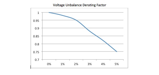
The National Electrical Manufacturers Association (NEMA) standard MG-1 defines the maximum voltage unbalance to be applied to an electric motor as 5%. However, it does outline that a derating factor must be applied to a motor operating with a voltage unbalance.

Voltage unbalance is relatively simple to calculate and requires the measurement of the phase to phase voltage of the supply to a three phase motor. The first step is to take all three measured voltages, add them together and divide by three. This will be your Vave. Next, you subtract the voltage furthest from the Vave, change it to a positive value, and then divide by Vave and multiply by 100%. For example, if you have Va-b = 465V, Va-c = 480V, and Vb-c = 467V, then (465V + 480V + 467V)/3 = 471Vave. Then ((480-471)/471) x 100% = 1.9%. When applied to the chart above you would then multiply the horsepower or kilowatt rating of the motor times 0.95. In effect, a 10 horsepower motor would have to operate as a 9.5 horsepower motor. It is also prudent to understand that the service factor should not be considered, so if the above motor had a 1.15 service factor, it would not be derated to a value of 0.95 times 11.5 horsepower.
While many mistakenly use current unbalance to determine the condition of a machine, these values can be used to trigger a review of the voltage balance of the machine. Another trigger would be a loud electrical humming or electrical growling noise, which would indicate a possible single phasing condition. The single phase condition involves the complete loss of one phase. A lightly loaded motor may run for an extended period of time while single phased with the remaining phases not drawing enough current to trip a standard overload. Special overloads are available, however, that can be used to detect voltage unbalances and single phase conditions.
Other than utility issues, such as loss of only one phase coming into a company, what other conditions will cause phase unbalance?
- Damaged conductors and loose/open connections;
- Starter contacts worn or overloads failing;
- Improper transformer taps;
- Transformer problems;
- Too many single phase loads on one phase of transformer(s);
- Power factor correction capacitor problems; and,
- Circuit impedance problems.
Once a voltage unbalance is detected, it becomes very important to identify the cause. However, if you do see a current unbalance with a low voltage unbalance, you can see if it can be corrected by rotating the phases and rechecking current. This is done by moving the lead from phase A to phase B, phase B to phase C, and phase C to phase A. This rotation does not change the direction of rotation. Re-check current and if the unbalance moves, then it is related to the motor. If it stays in the same location, or goes away, then it is supply related.
Smaller motors, in particular motors under 300 horsepower including submersible pumps, are wound and connected in such a way that a small (less than 7% required by NEMA) current unbalance with no voltage unbalance.
The failure of a motor due to a voltage unbalance or single phase condition is very specific. Windings overheat alternately with windings that do not, so the motor has alternating burned and unburned windings. The exact pattern depends on the motor connection, but the appearance is similar regardless. The excess heating in these conditions will reduce the motor life significantly, in addition to the motor operating with lower efficiency.
1Cooper Bussman Corp, Motor Protection: Voltage Unbalance and Single-Phasing, 2003.


Comments