Contributor: Rick Frauton, Senior Product Manager
Introduction
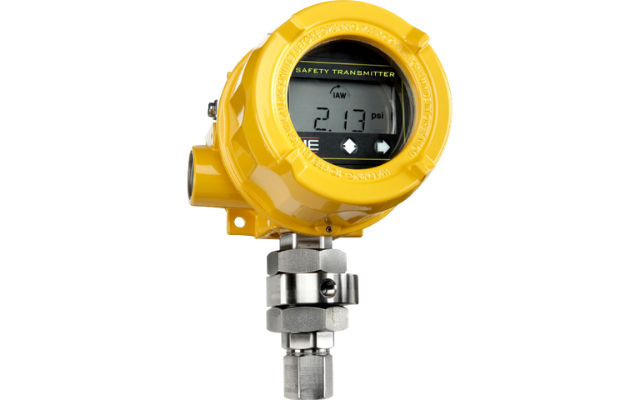
The new One Series Safety Transmitter has been receiving lots of attention from engineers involved with designing safety instrumented systems (SIS) for their hazardous processes. Why? What makes the One Series Safety Transmitter different from other transmitters currently available for safety applications?
Product Description
The Safety Transmitter allows users to validate the performance of instrumentation, alarm when the device goes awry, quickly deploy the safety function, and confirm device actions if called to do so. No other transmitter provides a built-in high-capacity safety relay capable of switching high voltage and current. No other transmitter provides multiple choices for how it is used in a safety instrumented function (SIF):
- as a 2-wire loop powered safety transmitter with standard 4-20 mA analog output
- for added safety and risk reduction, a discrete IAW (I Am Working!) health status output
- for an indication that the programmable set point has been reached, a discrete SRO Status output
- for emergency shutdown (ESD), a high capacity safety relay (SRO) that re- spends within 100 milliseconds or less
With a simple loop power connection, the One Series Safety Transmitter provides a NAMUR NE 43 standard 4-20 mA analog output, just as you would expect from a transmitter. In this simple 2-wire configuration, the One Series Safety Transmitter delivers a Safe Failure Fraction (SFF) of 98.6%. By adding another 2 wires and monitoring the IAW Out-put, the integrity of the analog signal is confirmed, allowing the SFF to jump to 98.8%.
Case Study
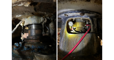
This application requires monitoring a process that produces high-pressure steam. The SIF in this case is to release steam pressure if it gets too high, preventing tank and pipe ruptures and potentially killing someone in the area. The 4-20 mA signal is sent to the safety PLC for monitoring and trending.
High steam pressure used in Cyclic Steam Stimulation and Steam Assisted Gravity Drainage applications is vital on this mobile skid, necessary to inject into the ground for loosening up trapped oil sands crude. If steam production stops, the extraction of the heavy crude will also stop. If the steam pressure is released to the atmosphere and the boiler is shut down, more than 2 hours is required to get back up and running. Every hour represents about $14K of crude pumping so it is essential to produce enough steam at a high enough pressure to keep that heavy crude/sand mixture moving!
In the above scenario, the operator received a warning (only) from the One Series Safety Transmitter. Although the steam pressure was trending upward, he was able to determine that this data is real (trustworthy) and he needs to check for other reasons for the increase in pressure. Without the IAW signal to verify the integrity of the 4-20 mA signal, the operator may have wrongly accused his transmitter of providing invalid pres-
sure readings.
Taking it to the next level – a case study
The operator noticed that the trend in steam pressure continued to rise. It was time to take some action before the dreaded shutdown occurred, releasing the steam pressure and shutting down the boiler.
Let’s recap what we know so far
Looking at the 4-20 mA signal, the pressure is trending upward at a rate of 1 PSI per hour. We have about 2 more hours to determine the cause of the pressure increase before the boiler trips and steam is released to the atmosphere. We know the integrity of the signal is good (IAW is closed). What other possible configurations for the One Series Safety Transmitter might have helped us with what was about to happen?
Choosing to monitor the SRO Status, we know that the setpoint, which was set safely below the point where a rupture can occur, has not been reached. If this were a voting logic SIF, we would have used the SRO Status and IAW Outputs to provide the safety PLC with this vital information to facilitate the voting logic scheme. But the HAZOP analysis didn’t require voting logic so we must totally rely on this transmitter’s signal. Thankfully the IAW Status output is monitored, providing some peace of mind.
The steam pressure dump valve needs to open quickly. As a result, the engineers decided to open the valve directly from the One Series Safety Transmitter, without the time, overhead, and complexity of performing that safety function through the safety PLC. This provides the fastest possible means of actuating the valve – within 100 mS. If it takes any longer than that, we run the risk of rupturing the tank or the piping.
It is vital that we can confirm the ability to open that valve or an accident will certainly occur. This additional safety check goes beyond the IAW Output algorithm’s ability to check the SRO’s integrity. Using redundant and diverse signal processing circuits and algorithms, IAW Output verifies that everything from the sensor’s A/D converter all the way to the signal that instructs the SRO to open, but not beyond that.
As a result, we also chose to turn on the SRO Monitor feature which allows us to determine the ability of the SRO to initiate the shutdown (open the pressure release valve). With this redundant safety feature, we can verify that the SRO is actually closed when the instrument sends those instructions. Conversely, if and when we need to open this safety relay to perform the safety function (dump the steam pressure), it will work! And if SRO Monitor found a problem with the safety relay, it will pass this information on to the IAW algorithm, opening the IAW Output and alerting the safety PLC that the safety transmitter’s SRO has become unreliable.
Back to the rising pressure situation
In the meantime, maintenance was called to check on the possible reasons for the increase in steam pressure. Boiler temperature readings were taken. They were abnormally high, producing too much steam. It was recommended to throttle back the boiler but 90 minutes has already elapsed before this was communicated. The pressure continued to rise. The setpoint was reached. IAW Output remained closed indicating that the integrity of the signal was valid. SRO Status signal opened. The SRO opened and initiated a steam release and a complete boiler shutdown.
After the shutdown occurred, operations began an event investigation. It was determined that the reason for the increase in steam pressure was actually caused by two separate issues, one downstream and one with the boiler process controls. Downstream, the steam injection nozzle was damaged by a drilling rate that was too fast, preventing the steam from exiting the nozzle at a normal rate. Had the SIF not released the steam pressure and shut down the boiler, the pressure would have continued to rise, reaching a dangerous level and causing an explosion.
The abnormally high boiler temperature was the result of a faulty pressure transmitter that is part of the basic process control system (BPCS). A ruptured diaphragm caused the readings from the BPCS transmitter to be erroneous, throttling the boiler to produce more steam when less was actually required. When the drill bit operator saw that so much steam pressure was available, he increased the drill rate beyond a safe level, damaging the drill bit’s steam injection head.
Avoiding the nuisance trip
In the case outlined above, the steam pressure relief valve opened and the boiler tripped, preventing injuries to personnel but causing a loss in crude production. Had the SIF tripped the boiler unnecessarily due to erroneous signals, several I&C technicians would have scrambled to get the boiler back up and running as quickly as possible. Anybody with experience knows that re-firing a hot boiler is a dangerous scenario, requiring careful attention to the sequence and a checklist.
Most smart transmitters indicate a detected fault by sending the 4-20 mA output to 3.6 mA by following the NAMUR NE 43 standard. When the safety PLC realizes that a sensor is reporting a fault in a simplex (1oo1) system, the SIF is no longer valid and an ESD will occur. This type of SIF does not provide any opportunity to investigate the conditions or the validity of the sensor’s signal to confirm the need for an ESD. This will cause the nuisance trip, shutting down the process unnecessarily.
The One Series Safety Transmitter allows monitoring the 4-20 mA signal and verification of its integrity by also monitoring the IAW Output. If the discrete IAW signal remains closed, the One Series Safety Transmitter’s signal is further validated, providing a warning and the opportunity to check for abnormal process conditions prior to the ESD.
It’s all about choice
The Safety Transmitter allows SIF design flexibility that can be used in several safety cases depending on the specific needs of the application. From a simple 2-wire transmitter tied into a safety PLC – all the way to a stand-alone combination sensor and logic solver that can initiate an ESD directly – providing whatever is required to satisfy the needs of the SIF including and up to safety integrity level (SIL) 3. Want to know more? Please contact the author.
To learn more about this topic and United Electric Controls (UE) capabilities, please contact the author at rfrauton@ueonline.com or see us at ueonline.com.