Tube Layout Pattern, Tube Spacing and Design Delta T.
Taco Comfort Solutions covers two topics here: hydronic radiant floor design considerations and high efficiency (ECM) circulator application. They interact meaningfully.
Taco as an industry tends to get locked into rules of thumb and simple recollection guidelines. In Rick Mayo’s 20 years of selling and training the proper installation of, and work with radiant heat tubing (1989 to 2009) — with seven of those years working directly for the manufacturer — they would show people several tubing layout patterns.
Among the layout patterns, they focused on as instructors were: single-wall serpentine, double- wall serpentine, triple-wall serpentine, counterflow serpentine, counterflow spiral, even some aluminum-based remodel techniques as well as specific joist bay configurations.
Though they would will show installers all the options, and why they might choose one over the other, the tendency would typically be to choose the easiest — the good old ‘path of least resistance.’ Just like most things in nature, we of the human species tend to prefer it that way, too.
Most, if not all these layout patterns can be used for space heating applications, some are particular to snow and ice melting. Which pattern is best sort of depends on the job at hand: considerations for floor construction methods, wet embedded or dry, floor covering R-values, Btu/h output or how tight you want the floor surface temperature profile to be (enabling even and consistent surface temperatures across the floor).
For wet (embedded) space-heating applications, the majority of contractors would continually pick the single-wall serpentine, as shown in Figure 1.
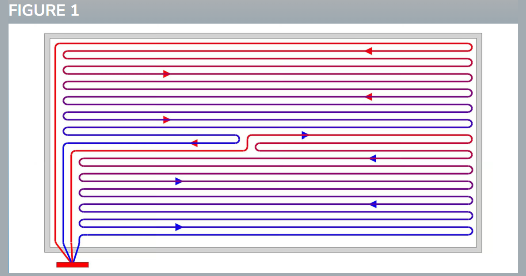
Single-wall serpentine layout pattern. IMAGE COURTESY OF MRPEX
This ‘simpler’ layout pattern is the main reason why we see 10° ΔT used as a “rule” so frequently in residential floor heating applications. Using the tighter fluid Delta T is one way to help the mean floor surface temperature remain closer, so that the sought-after barefoot comfort is there for occupants.
We generally don’t want occupants to be able to feel the floor getting cooler as they walk from one side of the room to the other (Now, whether the floor will actually ‘feel warm’ is a whole other lesson for another time; we’d title it: radiant floor heating and low Btu/h output requirements).
Let’s not forget that in wet applications the barefoot comfort can be achieved another way: by simply changing the layout pattern so the supply side of the loop runs parallel with, or next to the return. This is what the counterflow serpentine and counterflow spiral patterns accomplish, as shown in Figures 2 and 3, respectively.
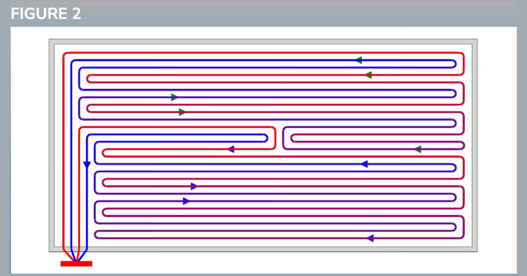
Counterflow serpentine layout pattern. IMAGE COURTESY OF MRPEX
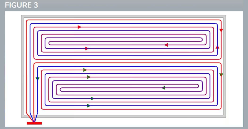
Counterflow spiral layout pattern. IMAGE COURTESY OF MRPEX
Because of the greater potential for consistent surface temperatures, we can deliberately widen the Delta T in our gpm calculation (aka the universal hydronics formula). Then, we could reduce the flow required for that zone, room or area being heated. In lieu of the 10° ΔT so often used, we can widen it to 15° or 20° F. This change would cut the gpm requirement by a third or completely in half.
For example: To deliver 100,000 Btu/h at a 10° ΔT, you would need 20 gpm. At a 15° ΔT, we’d need 13.3 gpm and at a 20° ΔT, we would only need 10 gpm. The ability to cut the circulator sizing in half is always good!
If installers change the tubing layout pattern, tighten up the tube spacing, shorten the loop lengths and stretch out the design fluid temperature Delta T, two key end-user benefits emerge:
- Smaller circulators, using less energy (wattage); and
- Lower fluid temperature requirements to increase overall system efficiency.
For every 1° C (1.8° F) increase in required fluid temperature, homeowners will see an increase of 2.5% in energy use for that appliance. The lower a fluid temperature, the better for most things hydronic.
Even Electrification Has A Role
Most readers in the hydronic heating industry know that when you lower the return temperature to a modulating-condensing gas boiler, you see a measurable efficiency increase. But here’s an example relating to hydronic technology much newer to the industry: the air-to-water heat pump (AWHP).
With these modern heating/cooling/DHW appliances, installers can lower the system required fluid temp by just 1° C (1.8°F), resulting in a reduction of electrical energy consumption by 2.5%.
Shorten loop lengths to reduce head requirements of the ECM circulator.
Another way to look at it is this: for every 1° C (1.8° F) increase in required fluid temperature, homeowners will see an increase of 2.5% in energy use for that appliance. Which brings us back to another reliable rule of thumb: the lower a fluid temperature, the better for most things hydronic.
Clearly, I’ve focused chiefly on hydronic heat, but the opposite is true for cooling fluid temperatures. For hydronic cooling, we want a system to use the highest fluid temperature possible, yet just capable of cooling an area.
To summarize (for wet embedded applications):
- “Build tight and ventilate right.” That, from my days of selling HRVs and ERVs — and a special thanks to Randy N;
- Know what the Btu/h load per square foot is; do a room-by-room heat loss calculation;
- Keep the tube spacing tight. This allows the use of lower fluid temps;
- Change the tubing layout to a counterflow arrangement. This will deliver more consistent surface temps;
- Widen the Delta T used in your gpm calculation to reduce the total gpm required; and
- If needed, shorten your loop lengths to reduce the head requirements of the ECM circulator.
ABOUT THE AUTHOR
Rick Mayo is the Western product and application instructor for Taco Comfort Solutions. He is an enthusiastic teacher with over 46 years in the industry. He combines his practical experience and technical expertise to ensure a productive, informative learning experience. Attendees can be assured to receive a solid understanding of hydronic and plumbing applications along with how products work within the plumbing and heating “system”.
Originally posted on Radiant & Hydronics. Photos courtesy of Taco Comfort Solutions.