Drive motor upgrade delivers improved flexibility and efficiency for Sulzer’s high-speed balancing facility
High-speed balancing facilities are used to ensure optimum performance of large pieces of rotating equipment, such as steam or gas turbines. Sulzer operates two of the very few independent facilities in the world and the site in Texas, U.S.A., recently underwent an upgrade project to improve both its flexibility and efficiency.
Electrical generators are vital to creating the electricity we all use in our everyday lives and with increasing demand reliable performance is essential to minimize the risk of blackouts. Sulzer is supporting these important assets with a comprehensive range of maintenance services, including high-speed balancing.
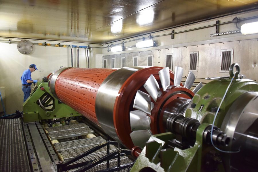
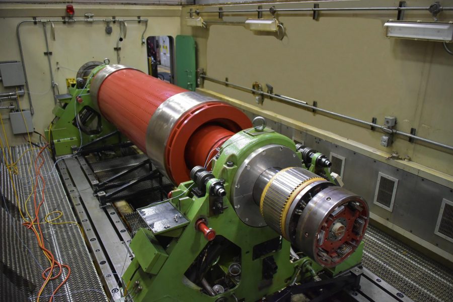
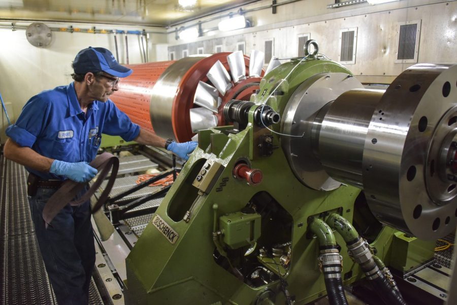
The independent, high-speed balancing facility in La Porte, Texas, is a specialist piece of diagnostic equipment that is designed to test some of the largest turbine rotors in the world. Equipped with a vacuum chamber, it can run complete turbine rotor assemblies at full operating speed, and beyond if necessary. The installation minimizes the time required to balance a rotor and the latest upgrade will reduce that time even further.
The bunker itself is designed to accommodate turbomachinery up to 30 feet (9 meters) in length, 8.5 feet (2.59 meters) in diameter, and up to 50’000 lbs (23 tonnes) in weight to speeds up to 40’000 rpm. Vibration diagnostics are used to analyze the radial vibration at the bearings to ensure that the best balance is achieved at operating speed as well as minimizing the deflection and vibration amplitudes during ramp up and coast down.

Sulzer can balance turbomachinery up to 30 feet (9 meters) in length, 8.5 feet (2.59 meters) in diameter, and up to 50’000 lbs (23 tonnes) in weight to speeds up to 40’000 rpm
Taking stock
The original installation used two 500 hp (370 kW) direct current (DC) motors that were installed in the 1990s. The two motors were connected inline, giving a 1’000 hp (740 kW) output, and could be operated independently. These were connected to a three-speed gearbox, which in turn was connected to a single-gear speed increaser. There is also the capability to add a third gearbox which is a turbo-drive.
The design of the drive system offered a maximum capacity of 150% of the motor power for a short period of time to start the rotor rolling. This equated to a maximum of 1’500 hp (1’110 kW) dual motor drive that could be configured to turn the rotor at, or above, its normal operating speed.
Having achieved the balancing assessment at a particular speed, a rotor needs to be brought back to a standstill to apply balance weights before the procedure can continue. With the old system, a regeneration drive acted as a brake, and also fed the energy generated by the slowing rotor, back into the grid.
Drive upgrade
The upgrade project would involve replacing the motors with alternating current (AC) alternatives, also rated at 500 hp, and new drives. The new drive motors can run briefly at 250% of the nominal rating, offering 2500 hp (1’850 kW) that can be used to start larger rotors rolling, increasing the capacity of the facility.
The new system remains as a dual-motor drive, but now the motors are always operated together and share the load between them, with the second motor fitted with an encoder that is used to calculate the speed of the rotor. The two drives are also linked together in a master/follower arrangement to ensure optimum performance of the motors.

The new drive motors can run briefly at 250% of the nominal rating, offering 2500 hp (1’850 kW) that can be used to start larger rotors rolling.
Gaining control
The original control system allowed the engineers to input inertia settings, which took account of many variables relating to the rotor being balanced including weight, length, and blade/impeller design. Rotors could be classified into one of six inertia groups and this would determine the configuration of the balancing drive system. These settings were fine-tuned over many years of operation but there was still some room for improvement.
To complete a balancing procedure, the engineers input the desired speed setpoint and the motors are engaged to start the rotor turning and then bring it up to the required speed.
Using vibration diagnostics to analyze the radial vibration at the bearings and the mid-span deflection is essential to ensuring that the best balance is achieved at operating speed as well as minimizing the deflection and vibration amplitudes during ramp up and coast down.
Process improvements
The new system uses precision torque control to regulate the speed of the rotors being balanced and this offers considerable refinements to the original system. The initial torque required to start the rotor turning can be minimized, reducing energy consumption. In addition, the torque required to bring a rotor up to a pre-set speed can also be optimized, being reduced as the target speed approaches.
The improved accuracy in speed control offers a more stable platform to conduct the balancing procedures, while the improved ability to accelerate and decelerate the rotor all combine to reduce the overall time required to complete the balancing procedure. At the same time, the regeneration drive continues to act as a brake and recover a large percentage of the energy used to accelerate the rotor on each cycle.
In addition, the gear ratios of the gearboxes have been programmed into the drive system and the encoder can calculate the speed of the rotor, based on the gear selection that is being used. The improved control system offers much greater precision and flexibility as well as reducing the amount of time required to complete a balancing procedure.
Long-term benefits
Despite having the same power rating, the new motors are considerably smaller than the originals, reducing the overall power train length by 3 feet (900 mm). They are also much more energy-efficient, reducing the overall costs for the facility.
However, the biggest gain has been in the control system, which is now a digital, touch-screen installation. The entire balancing facility can be operated from two human-machine interfaces (HMIs) that offer greater control and precision. The modern drives and the encoder provide better speed control, allowing the balancing software to deliver even more accurate results.
The next investment will involve upgrading the gearboxes, to allow the full potential of the new motors to be realized. In the meantime, the demand for this facility continues to rise as larger rotors can now be accommodated and customers’ projects can be completed on shorter lead times.
About Sulzer
Sulzer is a global leader in fluid engineering. We specialize in pumping, agitation, mixing, separation, and application technologies for fluids of all types. Our customers benefit from our commitment to innovation, performance, and quality and from our responsive network of 180 world-class production facilities and service centers across the globe. Sulzer has been headquartered in Winterthur, Switzerland, since 1834. In 2019, our 16’500 employees delivered revenues of CHF 3.7 billion. Our shares are traded on the SIX Swiss Exchange (SIX: SUN).
Throughout the Americas, Sulzer provides cutting-edge parts as well as maintenance and repair solutions for pumps, turbines, compressors, motors, and generators. We service our own original equipment as well as third-party rotating equipment operated by our customers. Our technology-based solutions maximize reliability and lifecycle cost-effectiveness.
For more information on Sulzer, visit www.sulzer.com


