Authors: Garrett Abbott-Frey, US Process Drive Offer Manager – Industry Business, Schneider Electric, and Jack Creamer, Market Segment Manager, Pumping Equipment – Industry Business, Schneider Electric
As Pump users and Pump system suppliers become increasing aware of the harmonics issues, they will find a variety of solutions from VFD supplier such as Schneider Electric. Let’s take a look at several solutions available, with both an understanding of the technologies involved along with the upsides and downsides of each.
As described in Part 1, Harmonic mitigation strategies depend on numerous factors and have varying benefits. Active rectification technologies provide the best harmonic mitigation performance in a small footprint, allowing flexibility in numerous applications. There are some large gaps however in the benefits between two level and three level topologies which we will explore in depth in the following articles. But first, a thorough understanding of how the input designs work is necessary.
Active Rectification
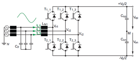
By replacing the six input diodes with insulated gate bipolar transistors (IGBTs), such as the ones used on the output of the drive, the input current wave shape can be controlled.
Figure 1 – Electrical Drawing of a 2-level Active Input Bridge
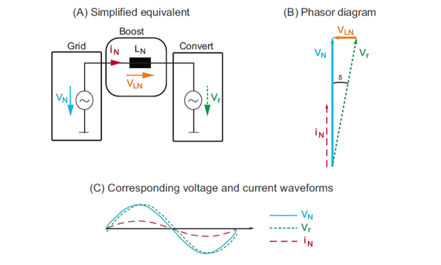
Figure 2(A) is a simplified equivalent model showing how two-level active rectification operates. The utility supplies a voltage source with a sinusoidal voltage vN with a known operating frequency fN. The converter system generates the voltage vr and the difference between the two voltages applies across the boost choke. The boost chokes are used as an energy storage element.
A positive voltage across this choke causes the current to increase, while a negative voltage across the choke causes it to decrease. To achieve sinusoidal mains currents iN in phase with this voltage, the converter system must generate a voltage vr that shows a small phase shift to the mains voltage vN. The corresponding phasor diagram and voltage and current waveforms are given in Figures 2(B) and 2(C), respectively. This is common among all active rectification topologies.
Figure 2 – Active Front End (AFE) Model
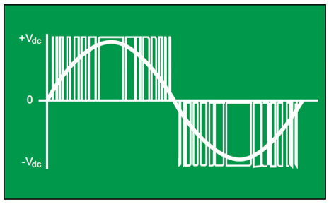
The pulse width modulated (PWM) waveform of the voltage from the IGBTs’ switching is smoothed by the input inductance to closer approximate a pure sine wave.
Figure 3 – Input IGBT Voltage and Current Waveforms
Disadvantages of this two-level approach are that some of the PWM harmonics from this input switching can appear on the power system, and some additional harmonics appear on the output of the drive to the motor.
The Three-Level Design of Schneider Electric Low Harmonic Drives
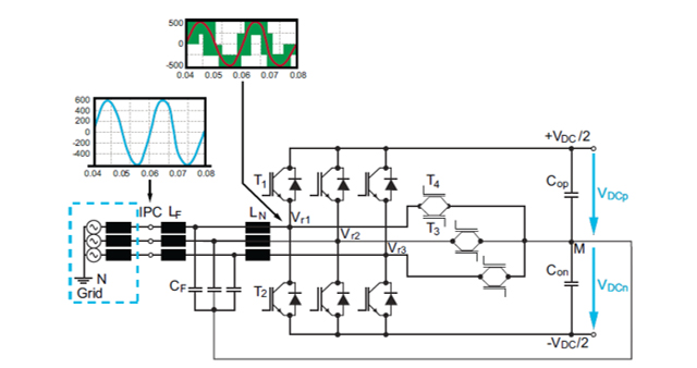
Three-level active rectification is used to improve input current waveforms. This is achieved by the addition of three bi-directional IGBT switches connected to the midpoint of the DC bus. This three-level topology also uses an additional common mode (CM) filter stage. The CM filter stage allows for high efficiency and behaves like a passive rectifier circuit in terms of CM voltage. Figure 4 illustrates the low harmonic solution using three-level active rectification.
Figure 4 – Schematic of the Three-level Design, Including LCL Filter at the
Input and High-frequency CM Filter Connection
In order to generate sinusoidal input currents in phase with the mains voltage, the current is shaped by the switching actions of the input IGBTs.
Three-level active rectification topologies can generate discrete voltage levels by either closing or opening particular bi-directional IGBT switches. Bi-directional IGBT switches are created by connecting two IGBT switches back-to-back, as shown by T3 and T4 in Figure 4. Two-level voltage converter stages with six switches are only able to generate two different voltage levels per phase. However, the three-level topology shown in Figure 4 is designed to generate three voltage levels per phase. Each phase can be connected to the positive DC bus +VDC/2 by closing switch T1 or, due to the corresponding freewheeling diodes, to the DC bus midpoint M by closing bi-directional switches, such as T3 and T4, or to the negative DC bus –VDC/2 by closing switch T2.
The average value of the converter voltage must implement the required 60 Hz voltage component for current shaping. This is because the converter must match the input voltage with a slightly offset matching voltage in order to arrive at a sinusoidal current flow. However, these slight voltage differences between the discrete voltage levels and the required average values cause additional current ripple in the boost chokes. These voltage differences are smaller in a three-level converter system where three voltage levels are available for current shaping compared to simple two-level topologies.
Schneider Electric’s low harmonic three-level active rectification incorporates a boost-type converter. Boost-type converters allow the DC bus to achieve voltages at higher levels than the mains peak voltage. With a 480 VAC line voltage, the DC bus voltage can reach 720 VDC. Switching losses are directly proportional to the DC bus voltage. Also dependent on DC bus voltage is the magnitude of the ripple currents carried by the boost chokes. Due to the design of the three-level topology with a DC bus midpoint, commutations are only half of the total DC bus voltage, resulting in significantly reduced switching losses. In addition to this reduction in switching losses, the DC bus voltage is not static but dynamic. It is adapted to match the mains behavior by use of a dedicated control algorithm. Due to this design, the switching frequency can be increased, which allows a more optimized, space-saving, active input stage.
Input Inductor-Capacitor-Inductor (LCL) Filter Design
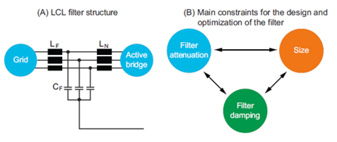
Schneider Electric’s low harmonic drive solution incorporates an input LCL filter design. This efficient, low pass input filter allows low-frequency voltage emissions to pass while attenuating (rejecting) high-frequency emissions. See Figure 5(A).
Figure 5 – LCL Filter
The performance of three-level drive systems is very dependent on this reduction of total voltage emission at the input terminals. At various multiples of the switching frequency, voltage emissions are reduced to less than 0.5%, substantially less than previous-generation, two-level technologies.
In addition to the attenuation of voltage emissions, there are other benefits. For example, in order to have an efficient input filter design, the amount of high-frequency voltage emission transfer to the mains must be minimized. The input filter design of Schneider Electric’s low harmonic drive systems reduces the level of high-frequency emissions transferred to the mains, resulting in minimal impact on the utility power system. These emission levels are at much lower amplitudes compared to 6-pulse technologies. However, the balance between this attenuation of high-frequency voltage emissions and overall efficiency of the converter must be considered. The size of the LCL filter is directly related to the level of desired attenuation. To achieve higher attenuation levels of voltage emissions, the overall size of the filter must increase. This filter typically operates in the range of several kHz for drive systems. This filter design is smaller than one operating at a lower frequency.
Higher attenuation increases the size of the filter, so a balance between filter attenuation, losses, size, and damping must be found, as shown in Figure 5(B). As shown in Figure 5(A), the LCL filter is composed of filter chokes LF, filter capacitors CF, and boost chokes LN. Together, these elements form a resonant tank. This resonant tank is susceptible to mains voltage variations from the utility, thus it is critical that this filter is properly damped.
However, reliably damping the resonant tank is typically difficult. An insufficiently damped input filter causes high currents in the filter capacitors, which would reduce the filter’s service life or even result in the breakdown of the filter capacitors. The filter chokes LF decouple the input stage from the grid and enable the filter to be well damped in all considered mains conditions. Oscillations of the filter are reduced, so the filter’s performance and service life are not degraded.
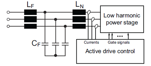
Schneider Electric’s low harmonic drive solution actively dampens the LCL filter by deploying a lossless control strategy. (See Figure 6). The control strategy is implemented in the controller software and does not require any additional passive components. The LC tank is directly damped by the converter stage itself. Thus, no additional losses occur due to passive damping elements and the efficiency of the low harmonic drive system is increased. The resonant frequency is determined by the filter choke LF, which establishes the tolerance to varying input mains power conditions.
Figure 6 – Lossless Control Strategy to Actively Damp the Input Filter
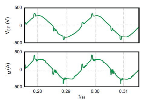
This active rectifier controller effectively dampens the LCL filter, resulting in almost no high-frequency oscillations in either the capacitor voltage or in the phase current. The three-level PWM waveform operates at 7 kHz. This higher switching frequency makes it easier to filter out the PWM than two-level AFE drives operating at 4 kHz or lower switching frequencies.
Figure 7 shows the phase currents of the LCL filter when being actively damped by the embedded control strategy. This clearly illustrates the overall effectiveness of the applied active damping strategy.
Figure 7 – Simulated Capacitor Voltage and Input Current When Damping Control is Active
This article is part of a five-part series looking at new technologies in harmonic mitigation – including the industry’s first three-level low-harmonic drive – designed to uniquely address the harmonics issue. For more information, please visit: goo.gl/zFuMXf.
About the Authors
Garrett Abbott-Frey is the U.S. Process Drive Offer Manager in the Industry Business of Schneider Electric. Based in Raleigh, North Carolina, Garrett brings nearly 5 years of professional experience to the role drawing from previous positions in OEM Machine Design and Electric Motor and Drives validation and testing. He currently focuses on Enclosed Drive Systems targeting the upstream Oil & Gas industry to support production process optimization for customers Artificial Lift applications. Garrett has led numerous training sessions on harmonics, drives commissioning, and other drives-related topics as well as recently publishing the whitepaper, “Transformation from Six-Pulse to Low Harmonic, Three-Level, Active Rectification Technologies.” He has a bachelor’s in Mechanical Engineering from North Carolina State University with a focus on Physics and Environmental Science.
Jack Creamer is Schneider Electric Segment Marketing Manager – Pumping Equipment, based in the United States. Mr. Creamer has more than 30 years in the Electrical Industry, and has been involved for 10 years in the Pumping Industry. He is involved in key industry organizations such as the Hydraulic Institute and Submersible Wastewater Pump Association, where he holds both Committee Chair and Board level positions. In his time in the Pump industry, he has help Schneider create numerous solutions that both enhance pumping efficiency and address issues such as maintenance and downtime.

