The accurate measurement of torque is a game-changer for pump reliability and efficiency.
Understanding Torque & Its Importance
One example of torque is to think of pushing or pulling a wrench to loosen or tighten a bolt. That turning force is torque, as Viking Pump explained in a Pye Barker Engineered Solutions guest blog. Torque can be calculated by using horsepower (hp), a constant and speed (rpm, or rotations per minute). Horsepower is the combination of torque and speed. If 1 hp is equal to 550 foot pounds per second, that is 33,000 foot pounds per minute. And when using horsepower for the calculation, the constant is 5252. Therefore:
T = (HP x 5252)/speed
Torque comes into play in pumping systems because in order for a pump to start, a motor must create the power needed to produce enough torque to start the pump and bring it up to the best operating speed. If the motor doesn’t produce enough torque, the pump will not start or it may operate at a speed that’s too low, as explained in an article by PumpWorks. When starting a pump, the motor has to be able to overcome the pump inertia and static friction (aka, stiction). With static friction, the frictional force resists force that is applied to an object. This object will remain stationary until the force of static friction is overcome, according to Britannica.
This means that, even when the pump is at rest, or 0% full load speed, the full load torque must be at 20% in order to overcome pump inertia and static friction. Then, as the speed of the pump increases, the torque needed declines.
What Are the Advantages of Torque Sensors?
Torque sensors can turn mechanical torque—the force used to turn the pump—into an electrical signal. With these torquemeters, users can determine the rotating device’s torque, speed, power and efficiency.
Because determining torque is such an integral part of operating a pump and doing so efficiently, a torque sensor device can lower costs associated with testing pumps and produce highly accurate data, which is necessary when selecting the right pump and motor combination for a particular application and facility.
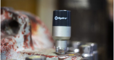
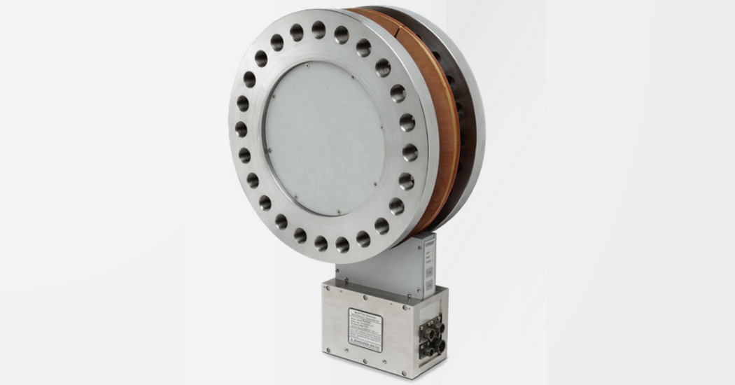 One type of torque sensor is the Bearingless Digital Torquemeter offered by S. Himmelstein and Company. This sensor is highly accurate, and its repeatability makes it a preferred sensor for power and efficiency testing. The Bearingless Digital Torquemeter does a few things differently than some other sensors:
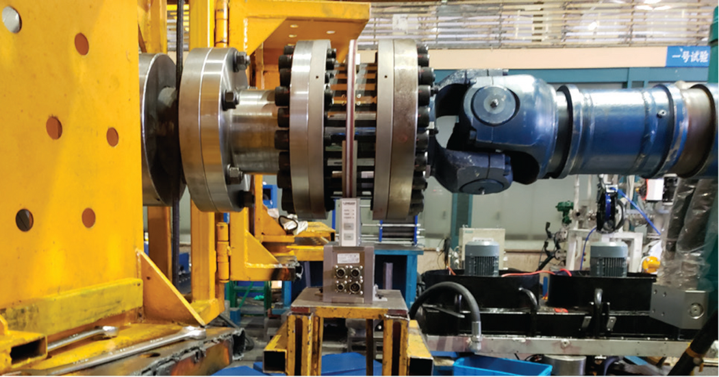
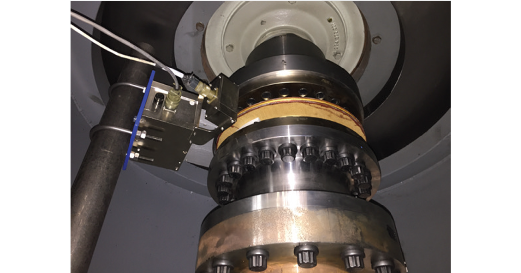
- The Bearingless Digital Torquemeter allows mechanical mounting advantages thanks to not using any bearings. The sensor has a flanged end configuration and is connected to the shaft between the pump and the motor using flexible couplings. These couplings compensate for the misalignment resulting from connecting two shaft ends together and the inability to get them lined up perfectly. Bearingless sensors have reduced maintenance as opposed to a transducer with bearings, since it is not necessary to be concerned with bearing wear and re-lubrication. In many pump testing areas—known as test cells—space is at a premium. This flange-style and coupling arrangement requires less installed space. In addition, in the case where pumps and motors might be close-coupled, it may not be possible to accommodate the space required for a shaft-style unit.
- The Bearingless Digital Torquemeter ensures accuracy. Users can expect the best possible measurement is being produced, with low combined error. Consequently, they can rely on one sensor, rather than needing a number of sensors, to maintain accuracy over a broader range of horsepower’s and still be within the recommended Hydraulic Institute uncertainty guidelines. Requiring fewer sensors results in costs savings. In fact, a single 0.01% Code J Bearingless Torquemeter, with more than 10 times the useful range of a 0.1% sensor, will still provide more accurate results than multiple 0.1% sensors handling the same torque/hp range. Again, this results in more accurate data, lower sensor capital cost, lower test bench cost and operational savings by eliminating sensor changeovers.
- The Bearingless Digital Torquemeter can feed data directly into a facility’s existing data acquisition system. Data is digitized on the rotor making it more immune to noise and signal coupling variations. The data is sent to the stator without physical contact where it is manipulated by multiple microprocessors. This digital output from the sensors is connected to software provided by S. Himmelstein and installed on existing hardware or the output can be imported directly into a user’s own data acquisition system.
- The Bearingless Digital Torquemeter can work in a vertical arrangement. In a vertical pump test setup, sensors must support significant hanging weight and potential extraneous thrust loading. With a bearingless design, the sensor is capable of handling the increased thrust loading evident in a vertical application with little to no impact on durability and performance. What Are the Advantages of Torque Sensors?
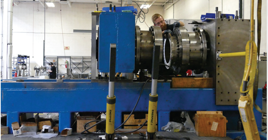
“Hydro Performance Test Lab, Inc. is an independent/aftermarket pump testing facility. We test pumps of all different types and sizes. Given our scope of work, we see many different vertical pumps with different design speeds. Using our test motor to operate these pumps has allowed us to use a known motor efficiency when calculated the pump input power. This “known” motor efficiency is nothing more than a nominal value that can be found on our motor nameplate. Since the motor efficiency is nothing more than a nominal value, we know that the pump input power calculation is only so accurate up to a certain degree. If we test a pump with a design speed significantly less than the rated speed of the motor, that motor efficiency value is now useless. After some research and redesign work on our side, we were able to incorporate the Bearingless Digital Torque Transducer into our dedicated machine train arrangement. Making the proper modifications to our machine train arrangement was fairly simple and allows for a very easy installation. Since this has been added to our setup, we have found that our test results have been more accurate and repeatable. We can now present our customers with more accurate and repeatable pump input power data, which also provides them with a more accurate efficiency curve and performance report.” —Thomas Papadakos, Test Lab Manager at Hydro Performance Test Lab
Additional Features
Two challenges that all users face with pumping systems are natural frequency and vibration during operation. With the latest S. Himmelstein Bearingless Digital Torquemeter, a short driveline—or a reduced axial installed length—offers significant advantages. The shorter driveline and high sensor stiffness results in higher natural frequency and reduced vibration. Higher natural frequencies gives more dynamic response and better accuracy.
These sensors are also designed to handle both overload and overrange. These two specification parameters are characteristic of all S. Himmelstein sensors. Overload represents a mechanical safety factor for the sensor element. It refers to the maximum load limit of the sensor before yield or physical deformation. In the case where the torque exceeds the sensor full scale rating, it will not have a mechanical failure.
 Overrange relates to the sensor’s electrical output signal. It represents how far the output voltage will extend beyond the sensor full scale before it clips. In the case where users operate beyond full scale, the sensor will still provide valid data.
The advantage to a sensor being able to handle overload and overrange is the data collected is free of errors from clipped torque peaks. Pump test data is not particularly stable, shows a lot of variability. Consequently, it is necessary average the data over longer time periods, and users will want to capture all of that data so they can analyze the best representation of performance. If the peaks are clipped off, the averaged data will be less accurate.
Finally, two additional features that provide peace of mind for users are the ability for the sensor to handle significant extraneous loads, and a fully accredited calibration certification.
Protection from influencing the torque signal is important, so high immunity to extraneous loads is essential. For example, with vertical applications, users would not want the hanging weight or thrust loading to create “cross talk” and influence the torque measurement. Therefore, the sensor must be able to withstand these loads without affecting the torque readings. The Bearingless Digital Torquemeter uses multiple strain gage bridges to cancel extraneous loads and also reduce the adverse effects of temperature gradient.
Understanding the criticality of measurements such as torque, speed and more, S. Himmelstein designed the Bearingless Digital Torquemeter to produce precise data and ensures that precision with accredited calibration documentation. The accredited, bi-directional ISO/IEC 17025/2017 calibration and true, bi-directional rotor shunt calibration check is standard. The user’s confidence and comfort with these measurements is imperative, hence obtaining a fully accredited calibration certificate for a unit is imperative. The user can be assured that the sensor was calibrated using primary standards traceable to national standards and performed in an accredited laboratory. Each sensor comes with a certificate of that calibration.
More Bearingless Digital Torquemeter Specs
- Large, noncritical rotor-to-stator gaps
- DC to 3 kHz bandwidth
- 13 selectable signal filters
- 10 selectable units of measure
- Fast max/min capture
- 0.00003% temperature compensation
- Remote zero
- Ranges from 250 pound force inches (28.2 Nm) to 22,120,000 pound force inches (2,500 kNm)
- 200%, 400%, 1,000% overload and dual-range models are offered
 About S. Himmelstein and Company
A manufacturer of torque sensors and signal conditioners in the United States, S. Himmelstein and Company has focused solely on torque since 1960. Himmelstein boasts an expansive product line and a highly accurate knowledge base. Located in Hoffman Estates, Illinois, Himmelstein continues to keep up with advances in technology to enhance and improve its torque sensors. Designing and manufacturing torque measurement transducers and instrumentation with significant advantages over competitive models and enhanced performance under real-world conditions is the company’s goal.
Himmelstein’s offerings include 200%, 400%, 500% and 1,000% overload models and the flexibility to select sensor mechanical overload, which allows optimal sizing of the sensor to suit the application, even in the presence of peak torques that exceed the average running torque. This ensures the best measurement accuracy for the application.
All Himmelstein torque transducers and instruments with high-level DC analog output voltages have significant electrical overrange (130% to 300% depending on model). This means that the output signal does not clip at full scale. By offering significant electrical overrange, Himmelstein transducers provide accurate measurement, even beyond full scale.
Himmelstein bearingless torque flanges are the best choice for dynamic measurement and control because the high torsional stiffness yields wider installed bandwidth and faster installed response. The company’s flanges also feature the industry’s highest overrange and greatest isolation from clamping and other extraneous loads, which reduce errors from clipped torque peaks and parasitic loads.
Superior temperature compensation results in sensor temperature performance that greatly reduces errors caused by drive heating and thermal gradients. This level of temperature performance allows S. Himmelstein and Company to offer dual-range torque transducers with high accuracy.