An expansion joint must perform several functions. The rubber joint is the most flexible part of a piping system, but this flexibility has a tradeoff. An expansion joint is usually the weakest component of a piping system and must be carefully selected for the application. Connected to a pump, it reduces vibration. If located in the connected piping, the expansion joint moves with the thermal pipe movement. It does all this while providing a seal under system pressure and at temperature – and maybe resisting a corrosive media. The keys to success are selection of the proper elastomer for the application, knowing the required movement, pressure and temperature, and proper installation.
What Are Rubber Joints Made of?
Simply, rubber. Or more technically, elastomers. Elastomers are made of high-molecular weight polymer chains, when vulcanized (or cured) can be repeatedly stretched and return to the original length. The different types of polymer chains, when combined with the curing method, give the rubber unique properties that make it suitable for various applications.

Table II from the Expansion Joints Piping Handbook, 8.0 Edition
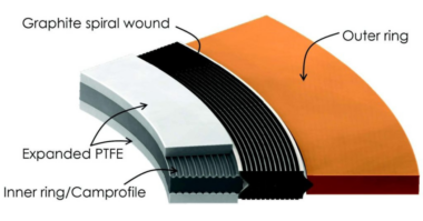
But there’s more than elastomers to an expansion joint. A typical expansion joint consists of three components: the tube, carcass, and cover. Let’s look at a typical joint starting from the inside working our way to the outside.

Typical expansion joint terms
Tube: The tube is a protective, leak-proof lining made of synthetic or natural rubber as the service dictates. This is a seamless tube that through the bore to the outside edges of the flanges. Its purpose is to eliminate the materials being handled penetrating the carcass and weakening the fabric. These tubes can be designed to cover service conditions for chemical, petroleum, sewage gaseous and abrasive materials.
Carcass: The carcass or body of the expansion joint consists of fabric and, when necessary, metal reinforcement.
Fabric reinforcement: The carcass fabric reinforcement is the flexible and supporting member between the tube and cover. Standard constructions normally utilize high-quality synthetic fabric. Natural fabrics can also be used at some pressures and temperatures. All fabric plies are impregnated with rubber or synthetic compounds to permit flexibility between the fabric plies.
Metal reinforcement: Wire or solid steel rings embedded in the carcass are frequently used as strengthening members of the joint. The use of metal sometimes raises the rated working pressure and can supply rigidity to the joint for vacuum service.
Cover: The exterior surface of the joint is formed from natural or synthetic rubber, depending on the service requirements. The prime function of the cover is to protect the carcass from outside damage or abuse. Special polymers can be supplied to resist chemicals, oils, sunlight, acid fumes and ozone. Also, a protective coating may be applied to the exterior of the joint for additional protection.
A rubber expansion joint may be compared to a tire in several ways. Both are made of reinforced rubber, customized for various conditions as necessary, and containing pressure.

Typical temperature ratings for tube/cover elastomers combined with reinforcing fabrics.
Types of Joints
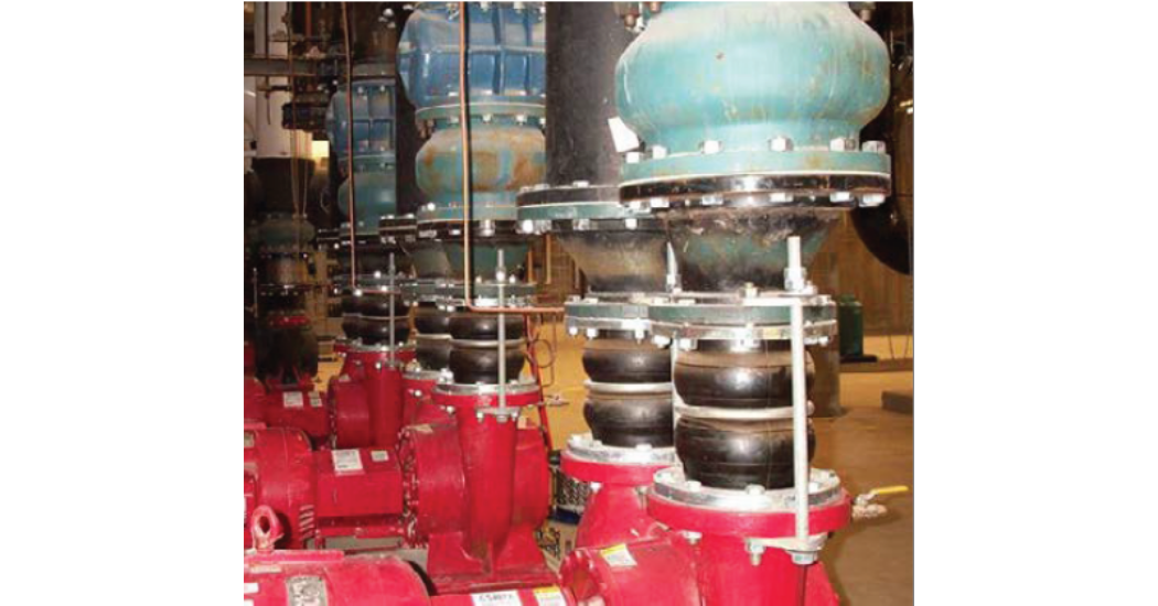
There are two main styles of rubber joints – spool and spherical. Spool-type joints have cylindrical bodies with steel reinforcing rings. This style of joint will typically also have arches to accommodate additional movement. Spool-type joints may be custom-manufactured for specific installation requirements. The sealing surface is a full-face flange.

Examples of spool-type expansion joints
Spherical Expansion joints utilize the body shape to provide a strong and flexible connector. The spherical body shape results in a uniform pressure distribution throughout the body, precluding the requirements for reinforcing steel and only including fabric reinforcement. Spherical joints typically have floating flanges and a bead seal instead of a full-face flange.

Examples of spherical joints (single and double spheres)
Application Considerations
Although a rubber joint appears very flexible and may be easily bent, twisted, and stretched, there are plenty of considerations when these joints are incorporated into a piping layout. Let’s look at what may be commonly overlooked with these joints.
Pressure Thrust
Pressure thrust sometimes surprises the installers, and it could be a rude surprise. Since a rubber joint has a flexible wall, and when put under pressure it will inflate like a balloon. The fabric and reinforcing steel will restrain stretching in the radial direction, but there is no real restraint in the axial direction. The only axial restraints will be external, in the form of either control rods or pipe anchors. As a result, the axial restraints will be subject to a pressure thrust force in addition to the spring force of the rubber body. The total force on a pipe anchor will be the pressure thrust added to the spring force of the rubber body. For an expansion joint with control rods, the pressure thrust will be restrained by the control rods unless the joint is compressed.

Typical expansion joint installed between two anchors
In the layout shown above, let’s say the pipe and expansion joint is 6”, the operating pressure is 100 psi, and the thermal movement of the pipe is calculated at 1”.
The pressure thrust from the expansion joint will be the pressure multiplied by the joint effective area. For this example, we’ll use an effective area of 52 square inches (this is unique for each manufacturer and can be found in the product literature).
100 psi x 52 sq. in. = 5200 lb thrust
If the axial spring rate is 345 lb/in (also specific to the manufacturer, but typical values can be found in Fluid Sealing Associations (FSA) Technical Handbook for Expansion Joint Piping) the spring force will be
345 lb/in x I in = 345 lb
The total anchor reaction would then be
5200 lb thrust + 345 lb spring force = 5545 lb per anchor
The spring force may be obvious, but the pressure thrust may not be. If the expansion joint is installed without restraints, the pressure thrust can easily move the connected pipe.
Another common installation has the expansion joint as a pump connector. For this installation, it is also common to include control rods to restrain the joint.
For this installation, no anchors would be required because the pressure thrust is restrained by the control rods. If we are using the same parameters as the anchored pipe example, the control rods would be restraining the 5200 lb pressure thrust with no thermal movement.
Elastomeric Joint Standards
The Fluid Sealing Association (FSA) is the main standards organization for rubber pipe expansion joints. There are three standards and one handbook to reference for more detailed information:
FSA Piping Expansion Joints Handbook, current edition (downloadable from the FSA) – this is THE source of information for elastomeric expansion joints. The handbook covers design and fabrication, application, installation, maintenance and troubleshooting of expansion joints.
FSA-PSJ-701-19 – Hydro and Vacuum Testing – covers hydrotesting and vacuum testing of non-metallic flanged expansion joints.
FSA-PSJ-702-19 – Installation, Maintenance, Storage – covers the installation, maintenance and storage of rubber flanged non-metallic expansion joints.
FSA-PSJ-703-19 – Guidelines for Elastomers – covers the typical properties of elastomers most frequently used for the tube and cover compounds in the manufacture of piping expansion joints for a wide range of applications.
In addition to these standards, elastomeric expansion joints can be fabricated to additional standards as required. Examples are ASTM F1123, NSF-61, and various military specs. Also, the FSA web site contains a wealth of information on the Knowledgebase at www.fluidsealing.com
Maintenance and Installation
Like car tires, rubber expansion joints have a service life and will be a maintenance item for the system. Unlike car tires, the service life is not measured in miles. The service life of an expansion joint depends on several factors including operating temperature and pressure, ambient conditions, movement, and proper installation. The best expansion joint for an application can be rendered useless if it is not installed according to the manufacturer’s instructions and following FSA recommendations.
The general rule for replacement of an expansion joint is five years for a joint in a critical service application. For joints not in a critical service, observe the joint at regular intervals and plan to replace after 10 years. Some joints can last as long as 30 years depending on the operating conditions.
Expansion joint failures are routinely traced back to installation problems. Here are some of the more common installation issues:
The expansion joint was used to make up for a pipe misalignment. The nature of a flexible joint makes it tempting to use it to compensate for a pipe misalignment. Don’t be tempted to do this. If a joint is used to make up for misaligned pipe, some of the rated movement will be taken up by the misalignment. At this point, the joint can be easily over-extended.
No anchors or control rods installed. This unfortunate situation will usually result in the joint over-extending itself under pressure. As described above, a lack of restraints will allow the joint to extend beyond its movement limits.
The expansion joint was not installed at the proper face-to-face length. This is similar to the joint making up for a pipe misalignment, except the pipes may be aligned but the space between the flanges is either too short or too wide to install the joint in a neutral position. Many times the joint is crammed between two flanges that are too close together. This can damage the bead of spherical joints, resulting in seal failure.
Loose bolts. Nearly every installation the author has visited has had loose bolts, loose enough to finger-tighten. Be sure to follow the manufacturer’s recommendations for bolt torque and re-tightening schedules.
We’ve only scratched the surface of the subject of rubber joints. To learn more about the subject, download FSA’s Piping Expansion Joints Handbook – and read it! You will not be sorry. It is a wealth of information on often-overlooked components of piping systems. The same authors of the handbook have also written several in-depth articles on the subjects mentioned above. And they are also free downloads from the FSA.