Water hammer (or hydraulic shock) is the momentary increase in pressure inside a pipe caused by a sudden change of direction or velocity of the liquid in the pipe. Water hammer can be particularly dangerous because the increase in pressure can be severe enough to rupture a pipe or cause damage to adjoining flow control equipment.
Physical Origins of Water Hammer
Water, an incompressible media, flowing within a pipe will possess three types of physical energy: Pressure, kinetic and potential. Pressure energy relates to the static or standing energy of the media, kinetic energy relates to the media velocity and potential energy relates to the relative elevation of the media (potential change in pressure) in the pipeline. All forces of pipe friction aside, the combination of pressure, kinetic and potential energy will remain constant at all points throughout the length of the pipeline.
Due to the physical Law of Conservation, where energy cannot be created nor destroyed, changing the magnitude of the kinetic energy, by changing the fluid velocity, will have a direct effect on the magnitude of pressure or potential energy elsewhere in the pipe. If the velocity of the liquid decreases (decrease in kinetic energy), the fluid pressure could increase (increase in pressure energy).
Water hammer most commonly occurs when water is flowing through a pipeline and a pump is stopped or a valve is quickly closed. The sudden halt in fluid flow in the pipeline will produce a pressure spike in the form of a shock wave, which will travel back and forth down the piping system, reflecting back from the end of the pipeline. The maximum velocity of this shock wave will be equal to or less than the speed of sound for that specific fluid.
For example, water at 70 degrees Fahrenheit has a sound wave velocity of over 4800 ft/sec (1463 m/sec). However, the dampening effect by which the material the pipeline is made from, affects and dictates the terminal velocity of the pressure wave. The shock wave will continue to oscillate back and forth down the pipeline, between the closed valve on one end and the end of the line, until the energy is absorbed, and the pressure soon equalizes in the pipeline.
If a pump stops or a valve rapidly closes while the fluid is in motion, two things can happen:
1) The line velocity moving toward the valve disc will rapidly decelerate and impose a sudden high (positive) pressure force and thus create a propagating pressure wave as defined above.
2) The opposite side of the valve, where line velocity was flowing away from the valve, will attempt to sustain the line velocity by working off of its kinetic energy. As the flow media attempts to maintain the line velocity, the pipeline will experience a sudden (negative) pressure force or vacuum, where the column of fluid will try to separate as the line velocity continues to move away from the valve. This is called column separation.
Column separation is a vacuum pocket where the vacuum pressure is continuous through the downstream end of the pipeline. Column separation creates a negative pressure, which can be sufficient enough to cause the pipe to collapse, especially in a circumstance when the pipeline is located on a slope where the water is flowing downhill. Valve placement is important to maintaining pipe integrity. Therefore, a valve should never be placed at the top of the hill without a downstream vacuum breaker valve in close proximity. Otherwise a valve that is closed at the top of the hill possesses a greater tendency to allow negative pressure to occur which can result in the collapse of the pipe.
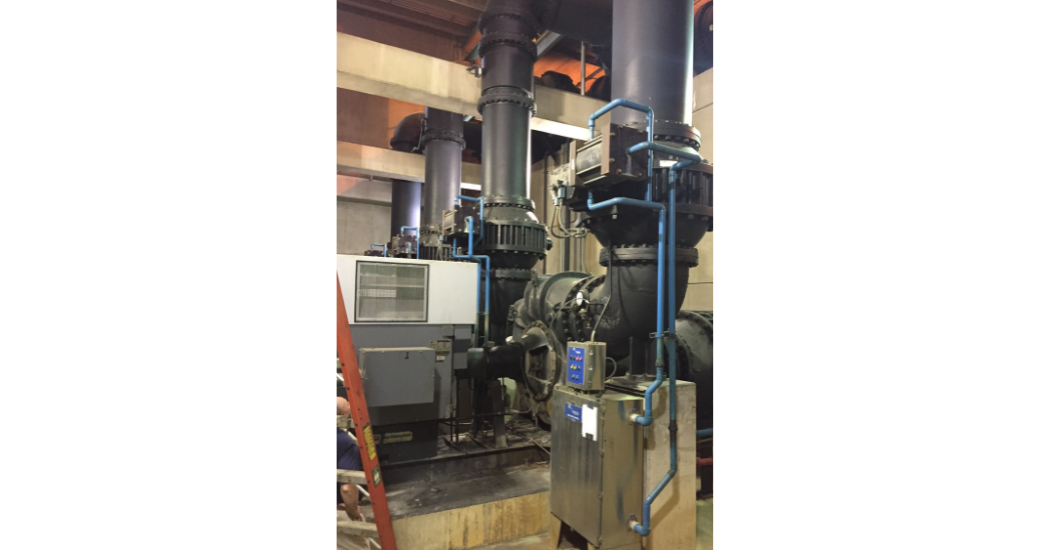
The use of a slow closing isolation valve on pump control will eliminate water hammer compared to using check valves. The check valve does prevent flow reversal, but at a cost. The rapid close action of a check valve will never be able to stop flow reversal before the pumping action ceases. Therefore, the slight flow reversal that suddenly stops against the back side of a check valve disc could produce a significant level of water hammer. The use of external air or hydraulic cushions to slow the closing motion of the check valve offers only some benefit. The single most assured way to eliminate any water hammer on a pump control application is to utilize a control valve that will proactively close on command rather than reactively close due to sensing flow reversal.
The Sequence of Operation for a pumping application should commence as follows:
Pump Start-up
1) Pump control valve is fully closed and pump is commanded to start.
2) Pump starts and pressure developed between the pump and the closed valve will be equal to or slightly greater than the downstream static pressure of the pipeline.
3) A pressure sensor senses the pipeline pressure and pump pressure have equalized and thus sends a command to SCADA to open the pump control valve.
4) The pump control valve will begin to open, but at a rate that has been determined (through a surge analysis) to not produce a pressure spike in the pipeline due to excessive flow surge.
5) The valve opens fully without producing a pressure spike and the pump continues its pumping obligation.
Pump Shutdown
1) After the pumping obligation has been satisfied SCADA will commence the pump shutdown sequence by first closing the pump control valve.
2) Due to the results of the surge analysis the minimum time required to close the pump control valve – without producing a pressure spike or column separation – has been defined and therefore the pump control valve will commence. Valve closure is performed however while the pump continues to run. If the pump were to stop running before the valve is fully closed flow reversal would occur and impart unnecessary harm, in the form of a pressure spike, to the pipeline and possibly backspin the pump, thus causing further unnecessary mechanical harm.
NOTE: the rate at which the valve can open or close must be independent of each other and field adjustable. To this end, electric operators use fixed gearing to develop the mechanical advantage required to operate a valve. Thus, it will only have one (fixed) rate of operation for both open and close. This approach is not a good option to control water hammer.
3) As the pump control valve approaches the full closed point a switch located on the pump control valve position indicator will trip and this will be the signal for SCADA to command the pump to stop.
4) The pump control valve closes and the pump stops flowing water. The end result is no pressure surges were produced and this approach can be used on all types of pump control applications.
 How to Minimize Water Hammer and Formulas for Doing So
A surge analysis can be performed on the piping system to determine the proper amount of time required to open and close a pump control valve. But sometimes pressure surges occur when a valve is manually closed too fast in the water distribution network. You can’t perform surge analysis on everything, so the best approach to pressure surges is to utilize isolation valves with slow closing (high number of turns to close) or characterized closing actuators. If you don’t know how slow to close a valve the below formulas can help. The proper opening and closing rate of a valve can be calculated and practiced to ensure safety and pipeline operation.
In order to calculate the correct valve closing rate it is first necessary to calculate the critical closing time of the pipeline being analyzed. To find this time s (in seconds) the equation is as follows:
s = 2L/a Eq. 1
Where:
L = Length of pipe in feet
a = Water Hammer Wave Velocity (ft/sec)
The next step is to determine the maximum head pressure due to water hammer, in excess of the initial head or initial pressure energy, in feet (h).
h = aV/g Eq. 2
Where:
a = estimated or derived water hammer wave velocity from Eq. 1
V = initial pipeline velocity (ft/sec)
g = Acceleration due to gravity (ft/sec2)
Now that you have calculated the excess pressure due to water hammer (in feet) (This is also considered the change in kinetic energy) and the critical time at which the pressure wave will travel from the valve to the end point of pipeline and return (in seconds), you can now use equation 3 to determine the desired or adjusted time required to close the valve in order to not exceed a satisfactory net pressure in the pipeline.
t = s x h/H Eq. 3
Where:
H = Net excess head due to water hammer at the valve in feet (this value is chosen as the “not to exceed” additive head pressure)
s = Critical closing time in seconds – from Eq. 1
h = Water hammer pressure above initial pressure in feet – from Eq. 2
t = Adjusted valve closing time in seconds
How to determine water hammer and solving for valve closure times:
EXAMPLE – 800 ft long ductile iron pipeline running at 8 ft/sec and initial pressure is 60 psi.
Using equation #1 determine the critical closing speed and wave velocity for the pipeline under review.
s = 2L/a
Where:
s = Critical closing time (seconds)
L = 1800 (Length of pipe in feet)
a = Water Hammer Wave Velocity (ft/sec)
There are general wave velocities that can be used to estimate the critical closing time – Material Water Hammer Wave Velocities (ft/sec)
PVC 1000 to 2000
Ductile Iron 3200 to 4500
Steel 2000 to 4000
However, when a precise wave time becomes necessary the accepted approach to determining water hammer wave velocity (a) can be derived using the following equation –
a = 4665(1/(1+K/E*d/t))^0.5
Where:
K = Fluid Bulk Modulus for water (300,000 psi)
E = Modulus of Elasticity of the pipe being analyzed (psi)
d = Diameter of pipe being analyzed (in.)
t = Wall thickness of pipe being analyzed (in.)
For this example, case we will choose the water hammer wave velocity (a) = 3300 ft/s
s = 2L/a
s = 2 x 1800/3300 = 1.1 seconds
Next, use equation #2 to solve for the maximum head pressure due to water hammer –
h = aV/g
Where:
a = 3300 ft/sec (from Eq. 1) for Ductile iron
V = 6 ft/sec
g = 32.2 ft/sec2
h = 3300 x 8/32.2 = 820 feet of excess head pressure due to water hammer 820/2.31 ft/psi = 355 psi)
Lastly, using equation #3 to solve for the required minimum valve closing time (in seconds) we will first determine the not to exceed contributing head pressure, which will be set at 46 ft or 20 psi.
t = s x h/H
Where:
H = 46 ft.
s = 1.1 sec. from Eq. 1
h = 820 ft. – from Eq. 2
t = 1.1 x 820/46 = 20 seconds or longer to close the valve on this line and not exceed an extra 46 foot of head pressure in this line.
You must remember that the pressure developed when you close the valve in the above calculation is additive (initial pressure energy + change in kinetic energy). So, the initial line pressure must be then added to determine the final line pressure. Initial 60 psi line pressure will increase to 80 psi after valve closes.
If in this example ductile iron pipe (rated to 150 psi) were used, it would be fine under normal conditions, but a rupture could result if the valve were to be closed quicker.
Solving for H and t = 3 seconds.
H= s x h/t = 1.1 x 820/3 = 300 foot of extra head (130 psi) could have a damaging effect on this line.
Other Causes of Water Hammer
- Rapid pump startup can induce a pressure spike due to pipe friction or air pockets in the pipeline.
- Rapid pump shutdown can act like a quick closing valve and create a quick change in flow velocity. This creates a positive pressure surge on the suction side of the pump and a vacuum surge on the discharge side of the pump. Worst case of these two surges will be the discharge side where column separation could occur.
- Check valve slam due to incorrect application. This occurs more than it should and is very costly to remedy the application. So, if in doubt consider using an alternate method to control flow reversal, such as a control valve or automated isolation valve.
- Air pockets in the pipeline or where check valves and pneumatic surge tanks are in close proximity to each other.
- Water column separation will not only produce vacuum in the pipeline but can also produce water hammer when the column rejoins.
Methods of Reducing or Eliminating Water Hammer
- Proper education and training of personnel on the dangers of water hammer and how to mitigate them through proper opening and closing of valves.
- Using soft start or variable frequency drive on pumps to reduce the possibility of creating damaging water hammer conditions.
- Reducing the velocity of the fluid in the pipeline to 5 ft/s or less to keep the potential of water hammer conditions to a minimum. Increasing pipe size is one approach.
- Using slow closing valves within the water distribution network. Any multi-turn operated valve is considered slow closing (gate valve, butterfly or knife) Any valves with a handle (1/4 turn operation) are considered quick closing and should not be used.
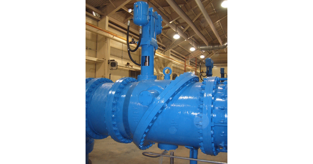
- Using cylinder operated valves for high service pump discharge applications will provide independently adjustable rates of open, close and emergency close action. This will eliminate the anticipated surge during pump start and stop and the unanticipated potential water hammer upon loss of pump power.
- Using air release valves along high points of the pipeline will remove trapped air that would otherwise act like air springs in the pipeline. Also, the use of air admitting (vacuum) valves will also curb potential pipe collapse conditions when a valve is closed too fast.
- Using surge tanks will cushion possible water hammer situations, but they can also exacerbate the potential for water hammer when used in close proximity to un-cushioned check valves.
In conclusion water hammer can be expressed in two ways – in the form of a pressure wave in a pipeline, where possible damage may result in a burst pipe, when a downstream valve is closed too quickly; or in the form of high vacuum, where possible damage may result in a pipe collapse, when the same upstream valve is closed. High upstream pressure and high downstream vacuum. The remedy to eliminating both of these potential disasters, when closing any valve, is to design into the valve the ability to control its operation rate.
Proper valve operation time can be calculated through surge analysis and thus can be completely avoided. Through proper pump station design the correct valve choice can be made to ensure when a pump stop or start sequence is initiated the isolation control valve will be “smart” enough to eliminate any surge upon pump start or hammer upon pump stop.
Electric motor operators provide only a fixed rate of control. Unless there is a “pulse” feature the electric operated valve provides little in the ability to adjust to varying (diurnal or seasonal) application conditions. Check valves utilizing hydraulic cushions can play a role in these applications, but only when application pressures and flow velocities permit the use of this type of valve. Verify if the specified check valve can actually provide the control to minimize or eliminate water hammer as advertised.
Unfortunately check valves that actually do control water hammer will carry a higher head loss burden. Optional valve features that claim to eliminate water hammer, such as external levers and weights or internal springs will produce more head loss, compared to a gravity check that has no ability to combat water hammer. This water hammer minimizing difference will be reflected in the respective valve head loss table. Verify the feature will perform as required.
Other ways to eliminate water hammer is proper training of personnel in the field on how to properly close down a water main will also eliminate further damage to fragile infrastructure. This begins by specifying manual actuators that require a minimum number of turns to open and this number should also be based upon a valve size range, (3”-20” valve requires a minimum of 30 turns, 24”-36” valve requires minimum of 40 turns, etc.). The lower number of turns to open the quicker the field operator can close the valve and thus produce a possibility for water hammer.


Comments