A concern often ignored in the specification of variable speed drives is the heat dissipation. The panel builder does care, because he needs to dimension the panel cooling, but what about the energy bill for the heat losses generated and the cost of cooling the motor control centres?
There is a difference
The difference in heat dissipation can result in a large difference in operational cost. First of all the heat from the drive comes from electricity consumed to modulate the output frequency to the motor, which is how the speed is adjusted. Also the built-in or required external filters have some cupper losses from the current over the coils.
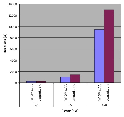
The graph on the left shows a comparison between three different sizes of drives from two different manufacturers. In the smallest sizes, there is only a limited difference, but in the 400 kW drive, the difference is more than 30%.
This higher difference in heat dissipation also requires additional cooling of the panels and the control room, which means even higher energy consumption.
In many installations, it is very common to use air-conditioning to reduce the heat in the control room to a level, which is within the specification of the electronics installed. As a rule of thumb the cooling of air require 3 kW cooling per 1 kW heat, so this is a very expensive way to remove the heat.
This shows how important it is to look at the technical specifications of a drive and to a higher degree specify, that drives should have a maximum heat dissipation of for example 3-4%, including all relevant filters and auxiliary components. Often manufacturers specify the drive efficiency based on the basic drive with an absolute minimum of filtering and other options.
Cooling concept of the drive
In order to reduce the requirement for air-conditioning of a control room, it can be very valuable to 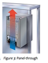 consider the cooling concept of the drive, when making a selection. There are ways to remove the heat dissipated from a drive, without cooling down the entire control room and without putting additional heat load on other equipment.
First of all there is the possibility to use liquid cooling. Liquid cooling means that the usually air cooled heat sink on the back of the drive is replace with a heat exchanger, through which a cold liquid flows to remove the heat from the drive. Typically around 80% of the heat dissipated can be removed through using this cooling concept.
One of the disadvantages is that there is a need for cold liquid, which in some case can simply be the water from a lake or from the sea (if the heat exchanger is seawater resistant). Alternatively a cooling unit is installed, which can cool down the water, which is recirculated to the drive.
Another problem is the introduction of liquid in an electrically charged environment. If there is any leakage, then the consequences could be a disaster, unless preventive measures have been taken to avoid water damage to equipment in the installation.
One way to avoid heating up the panels with the smaller drives is to make a simple “panel through” solution, where the heat sink from a drive is pushed through a hole in the back of the panel. Ventilators then secure an air flow across the heat sink, which will cool down the drive, as shown in Figure 3.
The air over the heat sink is typically allowed to be up to 45°C, which means that in most locations there is no requirement to cool down this air. Typically 75% of the heat from the drive is removed using this method, leaving only a limited amount of heating inside the panels.
The air can then be ducted away from the panels and directly into the ambient, thus reducing also the requirement for cooling in the control rooms.
A newer alternative is called “back channel” cooling. With this cooling air can be ducted through the regular air cooled heat sink on the drive, but without ever entering the control room. This is typically

available in larger drives, which are designed for standalone installation in the control room.
The drive is designed to allow optional air entry and exit directly from the back of the drive. The built-in fan is designed to cool the drive disregarding if the air is coming from the back of the drive or from the bottom, which is standard.
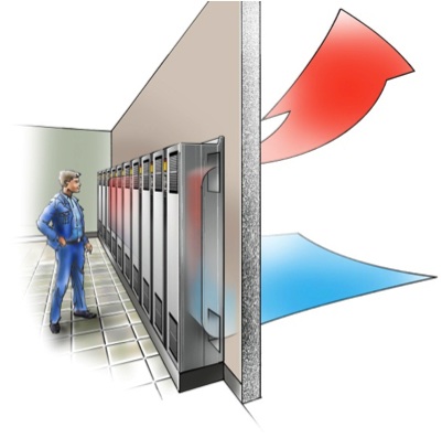
With this design the installation can be done directly against the wall. All air can then be circulated directly from the ambient and back to the ambient without heating up the control room and without passing over the electronics inside the drive. Figure 4 shows an example of this type of installation.
If the drives are installed in the centre of the room, it is possible to duct the air from the top of the drive and the air inlet can be from the bottom of the drive in the standard way, using the control room air to cool the drive, but without circulating the hot air back into the control room.
Up to 85% of the heat can be dissipated from the drive using this technology and it significantly reduces the heat load on a control room.
A rule of thumb is that the saving on the utility bill is about 8% per year compared to the cost of the drives. In a pump installation with 2 pcs 110kW, 3 pcs 200kW and 1 pcs 400kW, the reduction of heat dissipation over a year is 54MWh. If air-conditioning is installed to reduce the heat in the control room, this would equate an annual saving on the utility bill of 5,500 USD @10.21 cents per kWh, just for removing heat from 6 variable speed drives.
At the same time the air conditioning system should be dimensioned for the reduction in heat load of more than 18kW. If several smaller units are used for the cooling, this would equate 4×5.5kW air-conditioners. If we take the cost of establishing the back channel cooling into consideration, the saving would still be about USD 14,000. This roughly equates 12% of the cost of the drives.
So on top of the energy savings the drives provide in the application, there’s a total saving by using back channel cooling over a 5 year period of 52% of the drive cost.


[…] Information Sourced from: https://empoweringpumps.com/heat-dissipation-from-the-variable-speed-drive/ […]