Author: Heinz P. Bloch, P.E.
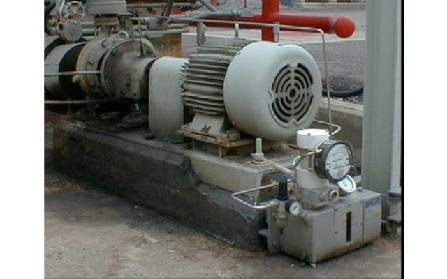
There are obviously some flaws in the grout surrounding the base plate in Fig. 1 above (on the other hand, the equipment owner invested in a very modern small oil mist lubrication unit, see foreground). Note the hollow space under the electric motor. Lack of support under motors often invites resonant vibration. Rigorous written installation procedures are needed and must be adhered to if long equipment life is to be achieved.
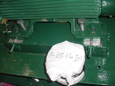
Note the alignment jacking provisions in Fig. 2 below where a knowledgeable purchaser specified an arrangement that allows insertion (and later removal) of alignment jacking tabs in the x and y-directions next to each of the four motor feet.

Fig. 2: Removable alignment jacking tabs shown inserted in three of four locations next to the two motor feet shown here
Portable jacking tabs, Fig. 3 below, (inserted in a welded-on bracket) allow driver alignment moves to be made. Thereafter, the jacking bolts are backed-off and the entire tab is removed. When jack screws are left tightened against the motor feet, motor heat and thermal growth might force the feet into these bolts even more, sometimes causing the entire motor casing to distort (Ref. 1 – see footnotes). Note, therefore, that backing-off jacking bolts should be one of many installation checklist items.
Never allow a contractor or your own workforce to install a process pump set with motor and pump already mounted on a baseplate. Remove driver and pump and install the baseplate in totally relaxed (stress-free) fashion. If necessary, field-machine the various mounting pads to be flat and co-planar before mounting pump and driver on their respective mounting pads.
Consider using epoxy pre-filled baseplates; fully understand what is achieved by using these monolithic blocks instead of adhering to other methods of purchasing “conventional” baseplates and instead of installing them in the “conventional” manner. You will never achieve your long-term reliability goals with a distorted or hollow baseplate. Bearings and mechanical seals will not ever achieve their stipulated design lives if you start with baseplate-induced compromises.
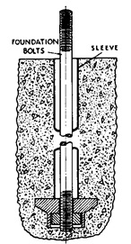
To ensure level mounting throughout, the base plate is placed on a foundation into which hold-down bolts or anchor bolts (Fig. 3) were encased when the reinforced concrete foundation was poured (Refs. 2 and 3). For proper stretch and long life, the anchor bolts in Fig. 3 must have a diameter-to-length ratio somewhere between 1:10 and 1:12. The anchor bolts are provided with sleeves or other flexible fill. The sleeves prevent entry of grout and accommodate the differing amounts of thermal growth of a concrete foundation relative to that of a steel base plate. There has to be this flexibility. For reliability and safety, accept nothing that deprives the installation of this flexibility.
References
- Bloch, Heinz P. and Allan Budris; “Pump User’s Handbook: Life Extension,” 4th Edition, (2014), Fairmont Publishing, Lilburn, GA, ISBN 0-88173-720-8
- Bloch, Heinz P.; “Pump Wisdom: Problem Solving for Operators and Specialists”; (2011), Wiley & Sons, Hoboken, NJ; ISBN 9-781118-04123-9
- Bloch, Heinz P.; “Petrochemical Machinery Insights,” (2016) Elsevier Publishing, Oxford, UK, and Cambridge, MA, ISBN 978-0-12-809272-9


