Early in the industrial revolution pumps were designed to be reciprocating plunger devices simply used for the transfer of water and other common liquids. The shafts were first sealed with strips of rubber coated woven cotton cloth cut into strips to form rings conforming to the dimensions of the stuffing box using the plunger diameter as the (ID) inside diameter of the ring and the bore diameter of the stuffing box as the OD (outside diameter) of the ring. This was suitable for the slow reciprocating movement of the plunger because relatively little frictional heat developed between it and the woven rubber coated cloth especially since it generally produced only a small amount of leakage for cooling and lubrication.
As improvements were implemented and rotary pumps with new shaft alloys were introduced conditions began to change. For example: After the introduction of high speed rotary pumps the rubber coated woven cotton cloth rings began to produce extreme frictional heat which made it necessary to require replacing the woven cloth with a more suitable cloth with higher temperature resistance. Braided asbestos rope saturated with lubricating oil coated with a self-lubricating graphite powder made its appearance and initially seemed to correct the problem.
Unfortunately, the rotary shafts were solid. As the abrasive asbestos wore the shaft it became necessary to replace the full length of the shaft which became a frequent costly procedure and included completely disassembling the pump. The next step in development came in providing a shaft sleeve capable of being installed over the otherwise worn section of the shaft.
In addition of limiting the wear to the inexpensive sleeve, there was considerably less assembly time involved and lower replacement costs. Although replacement costs were reduced, a new wear problem emerged. Common design practice required suitable clearances between the two parts to prevent interference between them as they were assembled.
The objective was to slide the sleeve over the shaft to transfer the wear to the relatively small area on the inexpensive replaceable sleeve. This design practice required suitable clearances between the two parts which was accomplished by machining a “relief” or a widening of the clearance between the shaft OD and the sleeve ID between the two ends of the sleeve. This reduced interference between the two parts during assembly. However, the larger clearance between the two parts produced a significantly larger dead space between the shaft and sleeve. This larger space interfered with the transfer of frictional heat from the source at the interface of the sleeve and the packing, slowing it down. As the frictional heat increased the “dead” non-circulating space trapped the heat from circulating into and through the shaft out into the atmosphere. This actually caused greater more rapid wear on the sleeve.
Frictional wear tends to accelerate over the relieved space (dead area) trapping heat between the two surface areas (sleeve ID and shaft OD). Wear was subsequently exacerbated by this new condition.
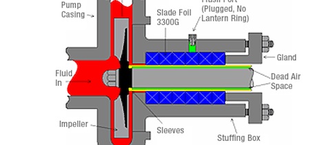
To correct this, a new design change was made to cool the sleeve to reduce the frictionally produced heat which itself had produced more friction and more wear. Therefore a lantern ring was installed to circulate a coolant (flush) over the sleeve to transfer the wear inducing, frictionally produced heat away from the stuffing box. This continues to be the practice in pump design today.
This produced another dilemma with the nature of the alloys used to manufacture the sleeve. Typically, the best wear resistant, corrosion resistant alloy is a 300 series stainless steel, typically 316SS. This alloy provides a condition of passivity which renders the stainless steel less reactive to chemical corrosion. However, the pacifying chromium in the steel alloy combines with free oxygen in the flush media to form a thin, invisible layer of a chrome-containing oxide.
The chromium forms a passivated layer of chromium oxide (Cr2O3) when exposed to oxygen. The layer is too thin to be visible, and the metal remains lustrous in spite of this change. The chrome oxide layer is impervious to water and air, protecting the metal beneath it. Also, this protective layer quickly reforms when the surface is scratched to pacify or rendering the surface less reactive chemically. This thin layer of chromium oxide (the passive film) packs neatly on the surface. The passive film self-repairing forms a stable layer only a few atoms thick. Even when the alloy is cut or scratched or otherwise disrupted it quickly recovers itself particularly in the presence of free oxygen. The chromium forms a passivated layer of chromium oxide (Cr2O3) when exposed to oxygen. The layer is too thin to be visible, and the metal remains lustrous. The layer is impervious to water and air, protecting the metal beneath. Also, this layer quickly reforms when the surface is scratched or buffed.
Flush water characteristics
Flush water commonly injected into the lantern ring to cool and lubricate characteristically contains free oxygen and is capable of producing an environment conducive to the formation of the passive chrome oxide coating. Therefore as the sleeve rotates against the mechanical packing seal the passive chrome oxide coating is transferred to the packing surface to produce an abrasive coating of chromium oxide which has an
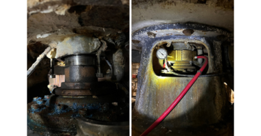
MOH hardness scale equal to 9, commonly used as a polishing compound on jewelers buffing and polishing wheels and this coating begins to polish the sleeve to death. An example of this destructive condition can be observed on sleeves that were used on clear clean water that have developed a deeply grooved but polished reflective surface when no solid contaminants were present to cause the wear. This phenomenon is technically described as “fretting corrosion” and is often associated with wear occurring under dynamic “O” rings. called “O ring fretting”. Each time the O ring moves against the shaft it removes or wipes the oxide coating from the shaft surface embedding it into the “O” ring surface to cause destructive wear.
If we were to return to the original equipment status, using solid shafts without a sleeve and add a suitable flush-free packing capable of conducting heat away from the frictional source causing a “heat sink” to develop in the stuffing box there would be no need for flushing the stuffing box with a liquid coolant.
Achieving flush free sealing is best based on utilizing the following conditions and suggestions.
Braided graphite packing having excellent thermal conductivity must be used in addition to the following suggestions and conditions.
Suggestions and Conditions:
1.) Solid 316SS shafts having a surface finish of 16 to 34 RMS. Reason: This surface roughness will produce “surface tooth” capable of transferring graphite from the vermiculated graphite packing to the metallic surface of the shaft thus filling surface imperfections to develop a composite surface finish of graphite and steel.. This condition has the remarkable benefit of reducing friction and dumping heat to the solid shaft where it can be transferred to the atmosphere or to some other suitable medium.
2.) Eliminate the flush water and allow the graphite packing to act as a heat transfer medium. The selection of correct type graphite sealing rings is critical to the success. When the packing is highly compressed close to its maximum density, the thermally conductive graphite sealing rings actually cause the stuffing box to act as a “heat sink”.
3.) Use 316 solid stainless shafts. In addition to eliminating the dead heat insulating cavity the wear on the used or worn shafts has been observed to improve the sealing effectiveness because the existing wear has produced multiple surface planes forming a tortuous fluid path similar to a labyrinth sealing device. Also, a cost savings is achieved because the solid shaft may be used several times before replacement is required.
4.) Take advantage of graphite’s ability to conduct heat 5 times faster along the graphite surface rather than through the body of the graphite foil. It should be noted that merely wrapping or spirally winding graphite ribbon around the shaft to form a sealing ring requires the heat to follow the spiral path of the ribbon rather than to transfer directly along the graphite surface from the heat source to the stuffing box exterior. A braided form of graphite yarn reinforced internally with carbon fiber provides better heat transfer especially if the ratio of carbon fiber to graphite foil is correct.
5.) Use a maximum of 3 to 5 highly compressed graphite sealing rings and then fill the balance of the stuffing box space with die formed metallic foil reinforced spacer bushings.
In summary of these recommendations: it is desirable to eliminate flush water in favor of a heat conductive braided lubricious graphite foil with no more than 3 to 5 sealing rings using spacer rings to fill the balance of the space. No lubricating oils are required to reduce friction.
Some of the benefits are:
A. Eliminates catastrophic failures
B. Eliminates flush waste
C. Prevents fretting corrosion
D. Lowers replacement costs
E. Pump disassembly not required
F. Replaces mechanical seals
G. May be adjusted to work leak free
Below is a case study from a Gulf Cost Refinery that shows the benefits of Flush Free Sealing:
A gulf coast refinery was using traditional packing in their 700°F hot resid or asphalt pumps. The pumps were all tandem with water-jacketed stuffing boxes. They used either a light oil or kerosene flush with a 3L3 or 3L4 configuration. They had a 3″ stainless steel sleeve turning at 1750 rpm and the packing cross section was 1/2″.
The problem was that the traditional packing was not able to run without major leakage & sleeve damage. Since EPA really frowns on oil on the ground, they were desperate to find something that would minimize or completely eliminate the leakage. They tried many brands of mechanical seals only to have them crash in this hot harsh abrasive application.
In September of 2000, 3300G Slade packing was installed in the first pump by compressing each ring very tightly then compressing the entire set as tightly as possible for 30 minutes then let it relax for 45minutes then tightened up to finger tight. It started with a very small leak but after 6 hours shut itself off & has had to have only minor adjustments since then. Since this time, several other pumps in this application have been packed with Slade 3300G with the same results. The customer says that this is not only a tremendous cost savings but also an answer to an environmental nightmare.
If you would like more information, please visit www.slade-inc.com
Author’s Bio:
Robert (Bob) Crosier entered the fluid sealing industry in 1963, first as a sales representative for the A. W. Chesterton Co. In 1969, he joined Garlock as Advertising and Marketing Services Manager. Later, in 1974, he joined the SEPCO Fluid Sealing Company as Vice President of Marketing and Sales. In 1988, Bob formed a fluid sealing manufacturing company which became Slade, Inc., now located in Statesville, NC, USA. Bob has been awarded 13 USA and International patents for the carbon and metallic reinforced graphite fluid sealing products manufactured by Slade. These patents teach a unique method of manufacturing ‘carbon fiber and metallic foil reinforced graphite foil’ braiding and weaving yarns, used in making braided packings and in the weaving of an 80” X 160” gasket sheet. He presently works at Slade as Product Development Engineer.