Author: William C. Livoti
In Part 2 of this 3-Part Series, we discussed why it is so important to develop and agree to a motor repair specification. In this article, Part 3, we dive into Owner’s Acceptance Criteria.
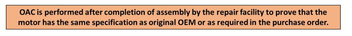
Owners Acceptance Criteria is developed based on the motor repair / re-wind specification as well as the criticality of the system the motor is driving. The OAC is defined in the motor repair specification and verified during the vendor surveillance process and during commissioning.
The acceptance criteria should be approached as a team effort, and the team should consist of anyone that has a vested interest in the system driven by the motor in question. For example, the team should include Reliability Engineer(s), Energy Specialist(s), Operations personnel, Purchasing, I&C, and Maintenance, Mechanical, and Electrical Personnel. Each team member sees and approaches business differently, and can raise specific concerns relative to their area of responsibility.
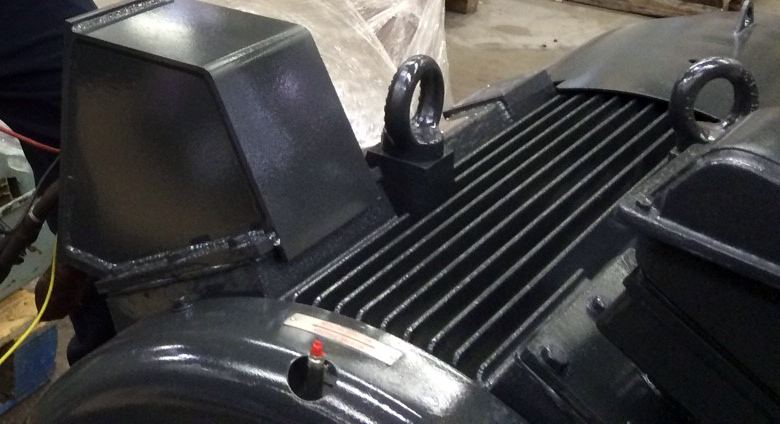
Example of Owners Acceptance Criteria at the Repair Facility
Cold Winding Resistance Test – The purpose of this test at induction motor testing is to measure the resistance of stator, rotor and exciter windings to ensure that the values calculated at 20°C (ambient) conforms to the technical specifications. These values are used for the calculation of temperature rise. The resistances are measured by the Voltammetric method at ambient temperature.
The test is performed by a current generator (greater than 10 ADC) and a voltmeter. The acceptance criteria shall be based on manufacturer approved procedure but usually phase to phase deviation should not be more than 2%, and max deviation from theoretical value should not be more than 5%.
Temperature Sensor Resistance Test – This test is done to make sure the continuity and homogeneity of each temperature sensor defined at 100 Ohms for 0°C. A multimeter or temperature direct reading probe is used for measurement. The acceptance criteria depends on test procedure, but normally should not be more than +/- 2° Celsius.
Bearing Temperature Test – The bearing temperature is frequently measured while the induction motor is in operation. The recorded temperature should not be beyond the acceptance range specified in the test procedure or the motor datasheet. Any abnormal vibration and noise should also be verified.
No-Load Bearing Temperature Rise – The induction motor shall run at the rated voltage and frequency, and each bearing temperature is measured periodically. Naturally, the bearing temperature will increase by passing the time. The temperature rise should not be more than the specified value in the induction motor testing procedure or motor datasheet. The procedure determines the running time and temperature reading intervals.
No-Load Curve & Losses Characteristics @ Induction Motor Routine Testing – The rotor shall run for a while to get bearing temperature and other variables stabilized. Then, the voltage is increased to the 120% of the rated value at the rated motor speed. Two data points are taken.
Subsequently, the voltage is decreased to 110%, and one more data point is taken. This process is continued until 60% of rated voltage, and several data points are taken. The voltage between phases, current per phase and absorbed power shall be measured at each data point. The measurement can be done by a power analyzer. The electrical calculation is made to obtain the actual losses.
The acceptance criteria shall be based on supplier approved motor routine testing procedure or as specified by equipment owner, but normally the calculated losses shall be less than of 110% of the theoretical loss.
Overspeed Test @ Induction Motor Testing – The overspeed test is performed to make sure that rotor speed can reach to the 1.2 times of the rated speed in 2 minutes. A speedometer is used to measure the rotor speed, and no noise, excess vibration and abnormal temperature rise shall be observed.
Bearing Vibration at No-Load Condition – Bearing Vibration test is performed when the rotor running at the no-load condition and the velocity vibration amplitude shall be measured in horizontal, vertical and axial directions. The velocity probe or accelerometer is used for measurement. The accelerometer measures vibration acceleration and not velocity; if used, the software converts the acceleration to the velocity by applying the calculation.
The acceptability of test shall be verified against acceptance criteria on the induction motor routine testing procedure, but the amplitude normally should not be more than 2.5 mm/s or 0.098 in/s (Root Mean Square Value).
Locked Rotor Current and Torque Test (SC/FLC & ST/FLT) – The purpose of the test in the motor routine testing is to calculate power factor, starting current, and starting torque. The test is done on the locked rotor condition. The starting current might be high, and the test normally is done at lower voltage, and result of the test extrapolated to the rated voltage.
A power analyzer is used for measurement. After measurement, the ratio of starting current to the full load current and starting torque to full load torques are calculated (SC/FLC & ST/FLT). The calculated values shall be verified against acceptance criteria provided in the approved induction motor test procedure.
Noise Level Test – The motor shall be run at the rated voltage and rotor speed at the no-load condition, and noise level should be measured at the 8 to 12 points depending on motor size and in motor perimeter at 1-meter distance from the motor. The noise level normally should not be more than 80 dBA, but the measured value shall be checked against acceptance criteria indicated in datasheet, test procedure, or by equipment owner.
Heat Run Test @ Induction Motor Testing – In this test, the machine is coupled with an appropriate piece of rotating equipment such as the pump, fan, compressor, etc.; then the load is applied to the rotor. All variable such as current, voltage, power, stator temperature, and bearing temperature are measured at the start and at 30-minute increments based on the test procedure. A power analyzer and temperature device are used for measurements.
After thermal stabilization (bearing temperatures), the motor is stopped, hot stator resistances are measured, and temperature rise is calculated based on following parameters:
- Cold state winding temperature
- Winding temperature at test end
- Coolant temperature at test end
- Cold state stator resistance between phases
- Stator resistance between phases at the end of the test
The stator temperature rise level shall be verified based on acceptance criteria addressed in the induction motor routine testing protocol / test procedure. This test is a key test in the induction motor testing.
Insulation Resistance Test – The test is one of the most important tests in the induction motor routine testing and is done to measure the winding insulation resistance of the armature, field poles, probes, space heater and bearings (if applicable).
A DC voltage is applied to the winding and the frame to which the magnetic circuit and other windings are connected. In the case the stator capacitance is too high for the instrument, the measurement can be performed phase by phase neutral open. For main windings, this measurement is performed twice: before and after the dielectric test. The measured resistance values shall be verified against acceptance criteria provided in the test procedure.
Example of Owners Acceptance Criteria on Site
Installation and commissioning are the first key steps to ensure that your motor will deliver the best possible performance. In many cases, the main reasons for failure during the first few months of operation are incorrect installation or lack of adequate care during commissioning. If important details are overlooked, the correct functioning of the motor can be compromised, and in some cases, the warranty is also affected.
In most cases the warranty period starts the day the equipment is commissioned. It is therefore essential that the plant has a full report confirming that all requirements have been fulfilled and all necessary tests successfully passed.
Check Points
Installation
- Mounting Surface (level)
- Motor feet, flat and co-plainer
- Coupling fit
- Alignment
- Electrical Connections
- Grounding
Start-up
- Vibration
- Bearing Temperatures
- Stator Temperature
- Terminal box (thermal Image)
- Performance test (under load) as outlined in shop test
Conclusion / Takeaways from this 3-Part Article Series
- Always use a qualified re-wind shop.
- A survey and qualification of each vendor service shop should be performed, and agreements made prior to repairs.
- Trust but verify with Vendor Surveillance.
- A quality re-wind can (if properly implemented) maintain original motor efficiency, however the loss in efficiency on re-winding depends on the techniques, processes and skill used to perform the re-wind, and usually results in a 1-2% loss in efficiency.
- No two motors are alike. Every repair / re-wind requires a clear concise repair specification – use USA EASA Standard and make sure they adhere to best practices.
- The prospects for a good re-wind are greatly improved if you keep good records on your motors and provide them to the repair shop. Repair shops often can’t get complete specifications from manufacturers.
- If a motor core has been damaged or the re-wind shop is careless, significant losses can occur.
- Owner Acceptance Criteria must be clearly defined in the RFQ / motor re-wind specification.
You may use the comments section below to request an example of a Motor Repair Vendor Capability Survey and the author will send to you upon request.