This article is a ‘sequel’ to What is the Purpose of Minimum Flow? published in February 2012 which discussed the technical rationale behind centrifugal pump minimum flow requirements.
This new article discusses the various minimum flow design options available including their respective advantages and disadvantages.
Designing for Pump Minimum Flow
Plant operational conditions including pumping rate of flow are governed by production demand. When pumping demand falls below the pump’s specified minimum flow, bypass recirculation flow is opened up to prevent problems with excessive vibration, overheating, flashing, or vapor lock resulting in a run dry incident. Pump minimum flow bypass recirculation is sort of like bank account overdraft protection. Fall below the minimum balance necessary to make payment and troubles follow.
The bypass piping, the valves, and the provisions for recirculation control comprise an ancillary system in support of the pump. Once the plant is built, the piping and valves are fixed; the pump geometry is fixed. The installation ‘is what it is.’ The typical AC induction motor’s rotational speed, other than slightly affected by load, is constant unless, of course, it is powered by a variable speed drive. The point is that adequate provisions for all operating scenarios including minimum recirculation flow must be considered in design of the system, plant operation, and equipment maintenance. Otherwise, in the case where the recirculation bypass control is inadequate or is not working properly, the plant operations team will be tempted to ignore the pump’s minimum flow requirement and not worry about consequences.
The plant engineering design stage is the time to plan for the near term and the foreseeable future pump operating conditions including bypass recirculation flow requirements. In the following section are brief descriptions of each design option for satisfying pump minimum flow including their principal advantages and disadvantages.
No Bypass
In the general population of smaller input power pumps, it is often the case that no bypass flow provision is required. Smaller pumps or submerged pumps may have no specified minimum flow requirement. Examples are residential swimming pool pumps and level-controlled sump pumps. While these pumping units may not be entirely immune to the problems resulting from operating at shutoff conditions, the risks may be acceptable.
Residential and commercial hot water recirculation pumps are often variable speed and are properly sized to operate efficiently, unthrottled, and without a bypass line. In other systems a single or multiple pumps are switched on and off to suit process demands. At the lowest flow demand conditions, a ‘jockey pump’ may have a variable speed drive (VSD). Pump operation is always above the specified minimum flow or in the case of a smaller pump with low input power, or with a submerged pump, it may be capable of operating continuously at shut off conditions.
Advantages:
- Setting aside transient conditions, such as start-up or shutdown against a closed discharge valve, if the system flow demand is always greater than that of the specified pump minimum flow, there may be no need for a bypass line.
- No extra equipment is added to the system that requires maintenance, can leak, or result in unanticipated failure.
Disadvantages:
- If there are operating scenarios where the pumping rate of flow can fall below that of its specified minimum flow, then there is risk of accelerated wear, overheating, or a run dry incident potentially causing catastrophic failure.
- Probably cannot be applied with flammable liquids where the risk of an overheating or a run dry incident is not acceptable.
Continuous Bypass
A fixed built-in continuous bypass line is shown in the piping and instrumentation diagram (P&ID) of Figure A. With relatively low-head pumps, this may be simply a piped bypass line with no restriction device. In this case, the bypass flow is simply a function of the piping and fittings sized for a given head loss to yield the pump minimum flow.
In the case of higher head pumps, a restriction orifice plate or a staged orifice design may be required to avoid cavitation and to limit flow velocity in the bypass line. Consideration must be given to start-up, continuous operation and shutdown scenarios, especially when multiple pumps are involved. Other considerations include: location of the bypass line with respect to the discharge check valve; bypass flow bubble formation in the receiving tank supplying the pump; the need for a check valve in the bypass line; scouring or abrasive wear; and possible need for a staged restriction orifice device to avoid cavitation.
Advantages:
- While the engineering considerations can be somewhat involved, the final design should be straightforward and involve no moving parts.
- Where the consequences of failure are high, or reliability is the foremost objective, this may be the best solution.
Disadvantages:
- Orifice plate wear can be a problem, depending upon velocities through the orifice openings, abrasives in the flow, and material selection.
- This solution also requires sizing the pump to meet the maximum system process demand plus the bypass flow, which entails larger equipment and installation sizing and a greater operational expenditure of energy.
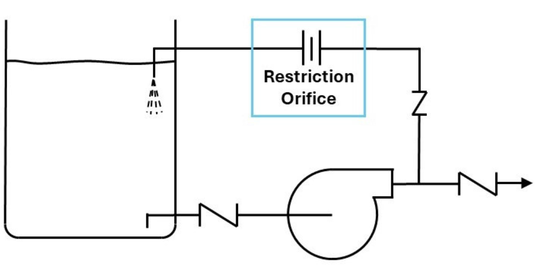
Figure A: P&ID for a continuous recirculation bypass.
Controlled Bypass Flow
Controlled bypass flow requires multiple subsystem components and process controls. A general P&ID diagram is shown in Figure B. The arrangement shown is based on feedback from a flow sensing device. Bypass control could alternatively be based on pressure or differential pressure feedback. Either an on-off type or a modulating type of bypass control could be used.
Advantages:
- An on-off controlled bypass flow system is less complex and therefore less subject to malfunction or failure.
- Modulating controlled bypass feedback instrumentation can be programmed for the required amount of pump bypass flow. It is a more energy efficient bypass flow solution.
Disadvantages:
- Complexity of the controlled bypass subsystem could potentially lead to unanticipated flow fluctuations or malfunctions.
- It involves higher costs relative to a continuous bypass arrangement.
- There is simply more that can fail including the risk of damaging the pump.
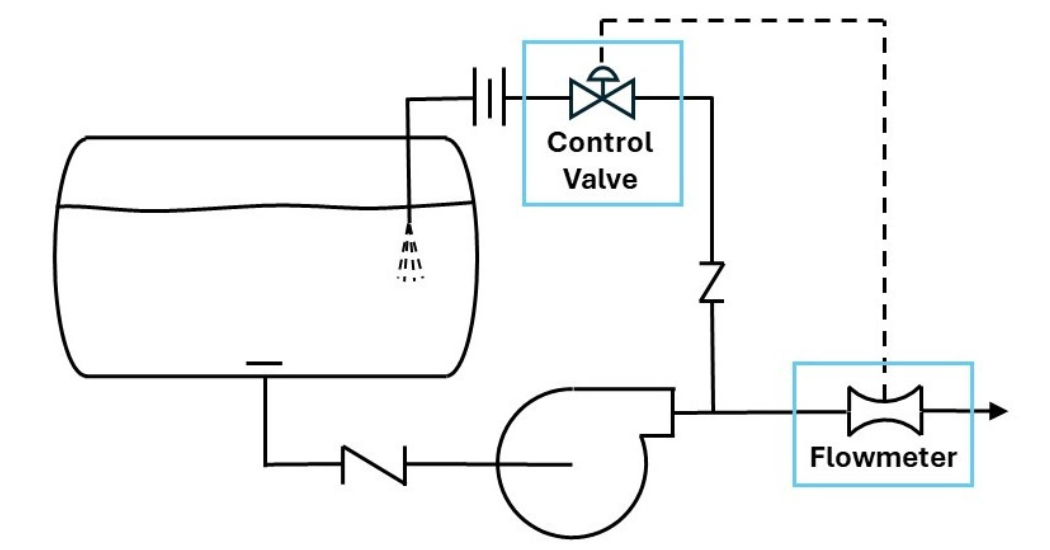
Figure B: P&ID for a controlled recirculation bypass.
Automatic Recirculation Control Valve
For an automatic recirculation control valve basic process diagram, refer to Figure C. An automatic recirculation control valve employs a flow activated check disc and an integral built-in recirculation bypass valve mechanically linked to the check disc. In the closed check disc condition, when there is zero process flow, the bypass valve is fully open. As the check disc opens, the bypass closes.
Advantages:
- An automatic recirculation control valve combines the functions of a check valve and a recirculation bypass valve into a single integrated mechanical unit.
- These are robust, reliable valves, provided the potential for cavitation and erosion are adequately addressed.
- They reduce the number of piping connections and eliminate packed valve stems. This cuts down on the number of product leakage paths.
Disadvantages:
- Automatic recirculation control valves are relatively expensive.
- The automatic recirculation control check disc supported by a center shaft presents greater flow resistance than a swing check disc. For certain continuous high flow applications, this may be an energy expenditure consideration.
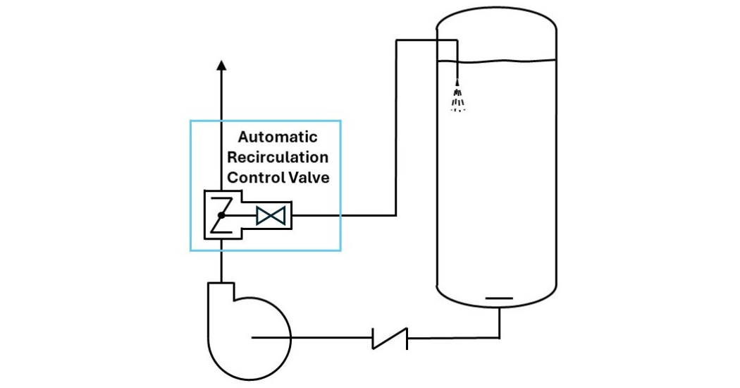
Figure C: P&ID for an automatic recirculation control valve bypass.
Variable Speed Drive (VSD)
A key attribute of VSD pump operation is being able to follow the pumping demand without throttling the flow. For an example pump performance and system characteristic chart, refer to Figure D. Note that regardless of the type of system curve, a VSD will enable pump operation to track system head versus flow requirements down to minimum flow or the VSD’s minimum output.
An evaluation of the process is necessary to determine whether VSD pump operation is a complete substitute for recirculation bypass. In the case of a static head dominated system or even a combined static head plus friction head system characteristic, it may be that at below minimum flow operating conditions, where pumping speed must be maintained to generate sufficient head, recirculation bypass is still required. In the case of a friction resistance dominated system, VSD control follows demand and the pump always stays out of the minimum flow region.
Advantages:
- May eliminate the need for an ancillary pump recirculation bypass system.
- There is substantial energy savings potential, especially when there is significant reduced flow pump operation. Variable speed pumping is most attractive for systems where the pumping demand is variable.
- A VSD reduces wear and tear on control valves and has soft start capability.
Disadvantages:
- First cost for a VSD is high.
- The VSD is a complex package of electrical and electronics gear that must be maintained.
- Malfunction or failure of the VSD, if there is no electrical bypass for across the line start, can affect process or plant reliability.
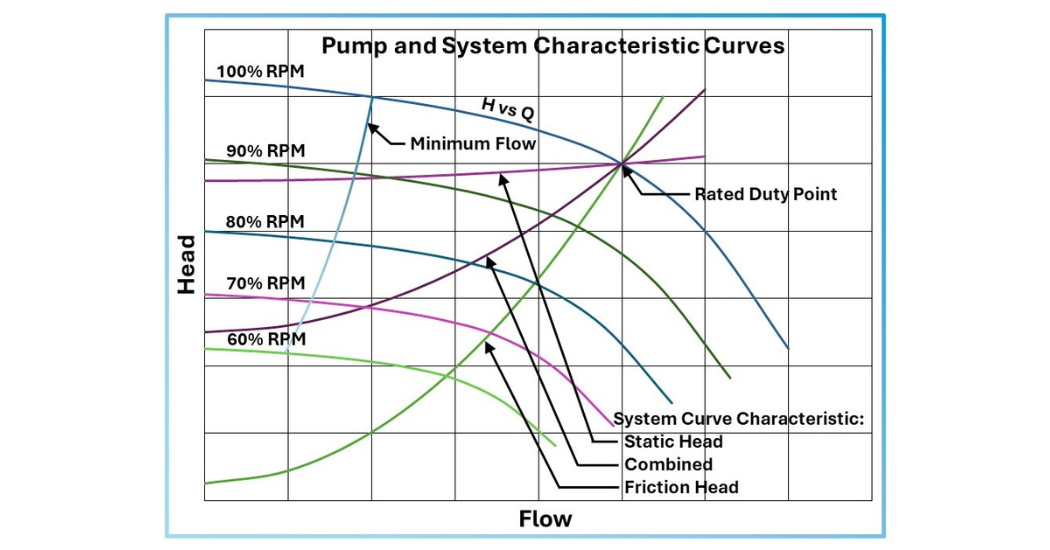
Figure D: Chart for pump performance and system characteristic curves.
Conclusion
There are several options to consider for addressing pump minimum flow. In some cases, the choice will be obvious. For example, many small input power pumps – particularly submerged units – do not require recirculation bypass flow arrangements. A high pressure boiler feedwater pump with a fixed speed drive, on the other hand, will likely have controlled bypass flow or an automatic recirculation control valve.
Each of the options presented above possesses key advantages and disadvantages. The specifying engineer should prepare P&ID schematics, performance curves covering the range of operating modes, and cost evaluations including installed costs, operating and energy costs, and maintenance costs. Recirculation for pump minimum flow should not be an afterthought. These ancillary systems are critical to the reliable operation of the pump.
For an independent evaluation of the pumping equipment for your system, contact an experienced consulting engineer who can help with your specific application.