This guide outlines and explains common environmental controls, such as piping plans, employed to improve the reliability of mechanical seals. No application is the same. Extended mechanical seal life in harsher applications is usually a function of being able to control the environment around the seal. Environmental controls have been established for this purpose.
References and Definitions
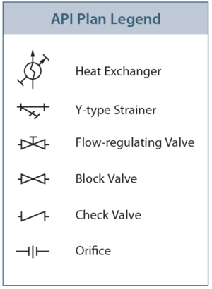
Environmental controls are support systems that are designed for use with mechanical seals. Each plan describes how the seal support systems are configured. The symbols used in the plans are described in the legend below.
Flow Control Orifices
An orifice is designed to limit the seal flush dilution and/or control the seal chamber pressure.
All orifices shall have a minimum bore of 3 mm (0.125″).
When multiple orifices are required, they shall be mounted in a series a minimum of 150 mm (6.000″) apart.
Seal flush systems using an external flush shall have provisions to monitor seal chamber pressure and flush pressure. A pressure gauge with a block valve on either side is recommended.
Heat Exchangers/Coolers
Heat exchangers shall provide enough flow to cool the seal per the manufacturer’s requirements.
The seal flush fluid shall be on the tube side and the cooling liquid shall be on the shell side.
Heat exchanger tubes shall be 19 mm (0.750″) in diameter by 2.4 mm (0.100″) in thickness, unless otherwise specified.
Heat exchangers shall have a removable head, using bolts or studs with nuts on each side. Tapped holes are not acceptable.
 Barrier/Buffer Fluid Tanks
The reservoir is part of the pumping system and shall be designed, fabricated, and tested to ISO 15649 (ASME B31.3) standards unless otherwise specified by local code or local plant specifications. The standard reservoir shall be a cylindrical vessel with fixed, ellipsoidal heads. A separate reservoir shall be provided for each dual seal installation.
The barrier fluid lines shall be a minimum of 12 mm (0.500″) for shaft sizes 60 mm (2.375″) or less and 18 mm (0.750″) for shaft sizes greater than 60 mm (2.375″). The tubing material shall be 300 series austenitic stainless steel (EN 1.4401). Austenitic schedule 80 stainless pipe can be used under the same guidelines.
All lines (seal connections) shall have a continuous slope upwards from the seal gland plate to the reservoir at a minimum of 10 mm (0.375″) per 240 mm (10.000″) of length.
The volume of liquid in the reservoir shall be a minimum of 12 liters (3 gallons) for shaft diameters of 60 mm (2.375″) and less. For shaft diameters greater than 60 mm (2.375″), the liquid volume should be a minimum of 20 liters (5 gallons).
Unless otherwise specified, the barrier/buffer fluid tank shall be equipped with a cooler.
Single Seals
API Plan 1
Internal recirculation of pumped fluid through the internal passage.
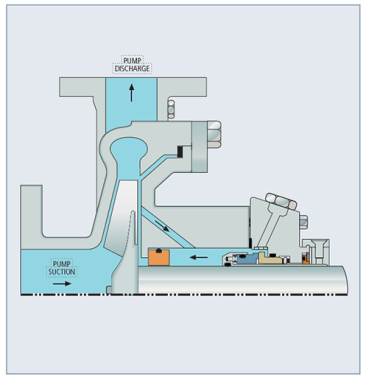
API Plan 2
External jacketed seal chamber. Dead-ended seal with no internal recirculation of pumped fluid.
API Plan 11
Discharge recirculation through an orifice to the seal flush port.
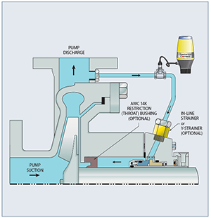
API Plan 12
Discharge recirculation through a strainer and orifice to the seal.
API Plan 13
Suction recirculation through an orifice to the flush port of the seal.
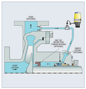
API Plan 14
Recirculation from pump discharge through an orifice to the seal while also supplying a suction recirculation from the chamber through an orifice to pump suction.
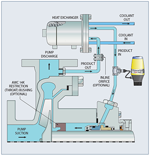
API Plan 21
Discharge recirculation through an orifice and a heat exchanger to the flush port of the seal.
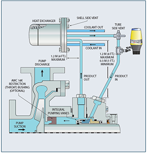
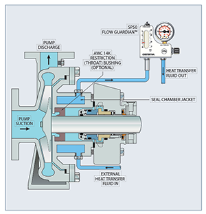
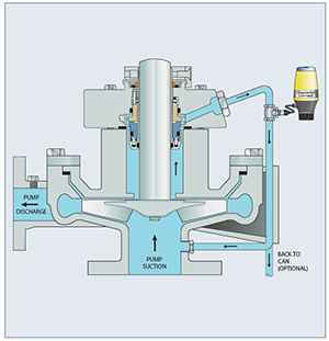
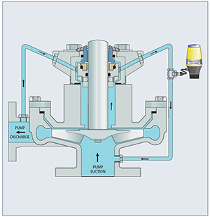
API Plan 23
Cooling provided to the seal chamber using an internal pumping device on a single seal.
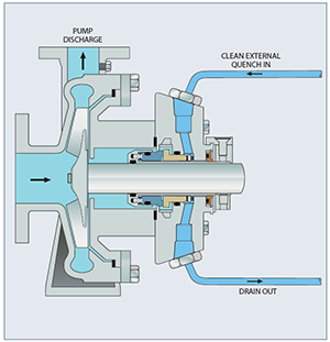
API Plan 32
Clean flush from an external source.
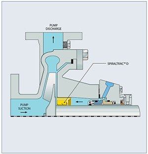
Chesterton Plan 33H
Used without flush to provide a cleaner sealing environment.
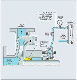
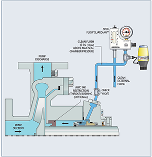
Chesterton Plan 33S
Clean flush from an external source in combination with a SpiralTrac environmental controller.
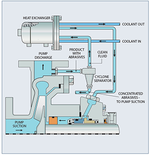
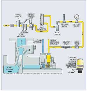
API Plan 41
Clean flush supplied from pump discharge through a separator, then cooled through a cooler.
API Plan 65
External drain piping that is alarmed to detect high seal leakage to atmosphere.
Double Seals
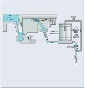
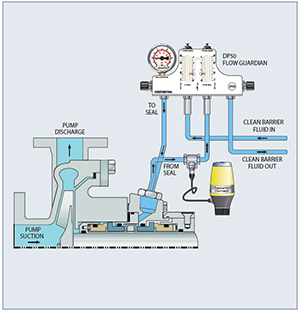
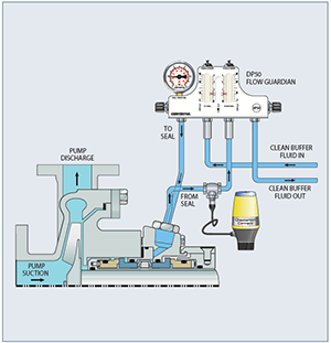
API Plan 52
External reservoir provides clean buffer fluid to the seal at a pressure lower than the seal chamber pressure.
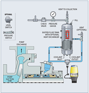
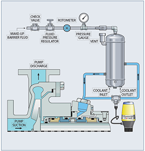
API Plan 53A
A pressurized, external reservoir provides a clean fluid to the inboard and outboard seals.
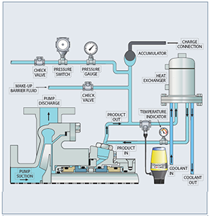
API Plan 53B
A pressurized, external clean fluid is delivered to the seal via an external bladder-type accumulator.
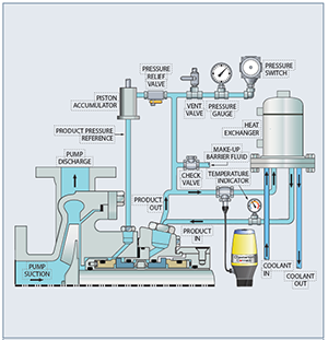
API Plan 53C
A pressurized, external clean fluid is delivered to the seal via an external piston-type accumulator.
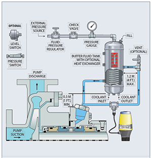
API Plan 53P
A pressurized, external fluid source provides clean fluid to the seal via an external pressure reservoir.
API Plan 54
A pressurized, external fluid source provides clean fluid to the seal via an external pressure header.
API Plan 55
Dual flow meter measuring flow in and out of the seal.
Quench Seals
API Plan 62
A steam or water quench.
Containment Seals
API Plan 72
A low-pressure buffer gas is regulated between the primary seal and the containment seal; typically nitrogen, is used as the buffer gas.
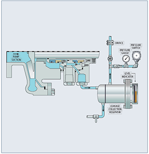
API Plan 75
A collection reservoir used with a dual containment seal to capture liquid that is collecting or condensing in the seal cavity.
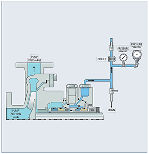
API Plan 76
Used with a dual containment seal where primary seal leakage is piped to a flare or a vapor recovery system.
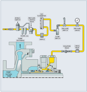
Gas Seals
API Plan 74
A barrier gas provided for a gas seal at a pressure higher than process
For assistance with using the best seal support system for your specific challenge, ask your local Chesterton office or contact A.W. Chesterton’s Ask the Expert service.