Part 1: The Cause
Three-phase electric motors are frequently regulated using variable frequency drives (VFDs). Drives allow precise control and sometimes large energy savings but also damage motor bearings. This is widely accepted but little understood. In this article, Aegis will try to shed some light on the three ways drives cause electrical bearing damage. In the next installment, Aegis will talk about how each of these modes of damage can be mitigated.
First, some background: Line voltage and current are sine waves at 50 or 60 Hz, depending on the country. With three-phase power, the voltage is balanced. The sum of the three-phase voltages is zero. They cancel each other out, so the line, and the motor, are neutral overall. When a motor is run on line power, its speed is determined by the line frequency.
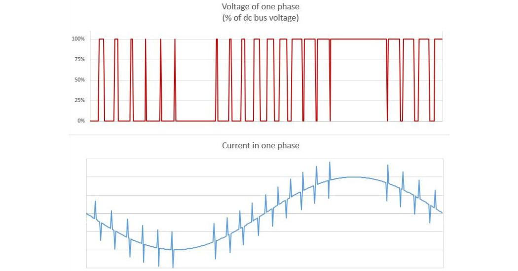
VFDs convert line power into a series of pulses of voltage in each phase. By controlling the timing of each pulse, the drive can run the motor at speeds much slower than the line frequency. But unlike line voltage, the drive output voltage is not balanced. The pulses in each phase do NOT cancel each other. Their sum is called the common mode voltage (CMV).
 The current from a drive looks less like a pulse and more like a sine wave. But every time the drive switches on or off, there is a spike in high-frequency current. Between the three phases of drive power, the current mostly cancel out. Except for those spikes. The sum of the current spikes in each phase is called the common mode current, which we’ll abbreviate CMI (“i” is an electrical shorthand for current).
Before moving on to the motor, it’s worth discussing the relationship between the voltage and current in each phase. The spikes of current are caused by large rapid changes in voltage from the drive. The rate of voltage change is called dv/dt. dv/dt is always large for modern drives because their switching is very fast. With a low-voltage drive, the voltage changes by hundreds of volts in under a millionth of a second. Medium voltage drives have even larger voltage changes.
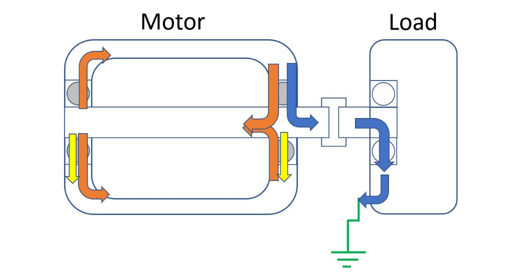
When the drive’s output wave reaches the motor, two things happen. First, the CMV electrostatically charges the rotor. If the windings are positive, this will attract electrons (negative) to the middle of the rotor, leaving a positive charge at the ends. This produces a voltage across the bearings, which can be measured as the shaft voltage. If the shaft voltage builds up high enough, it will arc through the bearing, damaging the balls and raceways. This shaft voltage discharge is often called rotor discharge current or EDM current, and is shown in yellow in the figure. EDM current may peak between half an amp to a few amps. It is a problem in all motors on drives, regardless of size. In small well-grounded motors, this is only damaging bearing current that drives cause.
Rotor discharge current depends mainly on the size of the CMV, not its rate of change. If dv/dt is decreased, the shaft voltage will increase less rapidly but will still reach the same peak value. If the peak voltage is high enough to cause arcing through the bearing, the damage will still be done.
Meanwhile, the high-frequency CMI leaks through the capacitance between the stator windings and the frame to seek a low-resistance path to ground/back to the drive. (The windings have high inductance, which means high impedance for high-frequency current.) This can also be described as the high dv/dt charging stray capacitance in the motor frame. Regardless of the terminology, this has two potentially damaging consequences.
In large motors, over 100 hp/75 kW, the CMI induces high-frequency circulating current. This current flows from shaft to frame through one bearing (orange) and back to the shaft through the other bearing (at right). This current’s mechanism is more complicated. Basically, as it runs to ground, the common mode current is not evenly distributed over the motor. This produces an unbalanced magnetic flux inside the motor. Electrons in the rotor and frame will “try” to circulate to counteract that flux. The resulting high-frequency circulating currents’ size can range from a few up to 20 amps.
The other side effect of CMI occurs in motors poorly grounded/bonded to the VFD. If the motor frame does not have a low-impedance path to ground, then the CMI can arc through the motor bearings, run down the shaft, through the coupling into the load equipment, arc through that equipment’s bearings, and then run to ground. This is called rotor ground current (blue). (Some sources confusingly call it shaft grounding current.) Rotor ground current can be several tens of amps, and is doubly destructive because it damages both the motor and the equipment bearings.
Both high-frequency circulating current and rotor ground current is caused by common mode current or, equivalently, the common mode voltage’s large rate of change.
Fortunately, all of these destructive bearing currents can be brought under control. In a future installment, Aegis will discuss mitigation strategies for each.