Author: Michael Huebner, Flowserve Corporation
Challenges of sealing hot applications
Many process fluids are at a temperature that can prove challenging for mechanical seals. High temperatures can result in low fluid viscosity, high vapor pressure, and coking /thermal breakdown of the process fluid. Reducing the fluid temperature in the seal chamber can often lead to improved seal performance and equipment reliability.
There are several standardized piping plans defined in API-682 which can achieve the desired cooling. While both can reduce the temperature, there are significant differences in the efficiency of the cooling and impact on the plant operations.
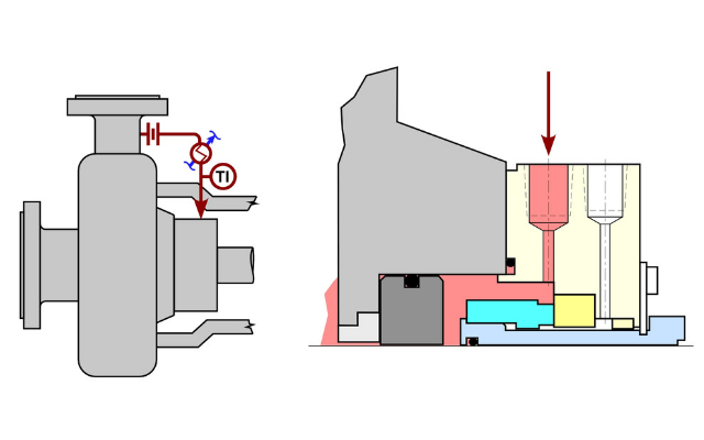
Piping Plan 21
Plan 21 is defined as a circulation of process fluid from a high-pressure region of the pump, through a seal cooler and flow control orifice, back into the seal chamber.
Pros
Since the process fluid is circulated through a cooler, the fluid injected into the seal chamber will be lower than the process fluid. The flow rate of the fluid and desired reduction in temperature will dictate the type and capacity of the seal cooler in the system. Both water-cooled and air-cooled seal coolers have been used successfully in the field.
A Plan 21 creates circulation due to the differential pressure in the piping plan. For this reason, there are generally no issues with overcoming friction losses in the piping and the seal cooler itself. This allows for the selection of a greater variety of seal coolers and more flexibility in the design of the system.
Cons
The greatest challenge with a Plan 21 is the amount of cooling which must continuously occur in operation. Process fluid enters the cooler at process temperature and it must be cooled to the desired temperature. This continual removal of heat can require a larger capacity seal cooler and higher demand for cooling water from the plant. Depending upon the conditions, it may also be difficult to achieve the desired temperature reduction.
In a Plan 21, the cooled process fluid is recirculated back into the pump casing and the process. This effectively reduces the process fluid temperature in the pumping system. Although this is often considered to have a negligible impact, it does result in loss of thermal efficiency in the process.
Process fluid enters the seal cooler at the maximum temperature of the process. In high temperature applications, this can result in fouling in water-cooled seal coolers. As high temperature process fluid enters the cooler, local boiling can occur. Most plants have less than ideal cooling water quality and the resulting boiling causes solids to build up on the heat transfer surfaces reducing cooling performance.
Piping Plan 23
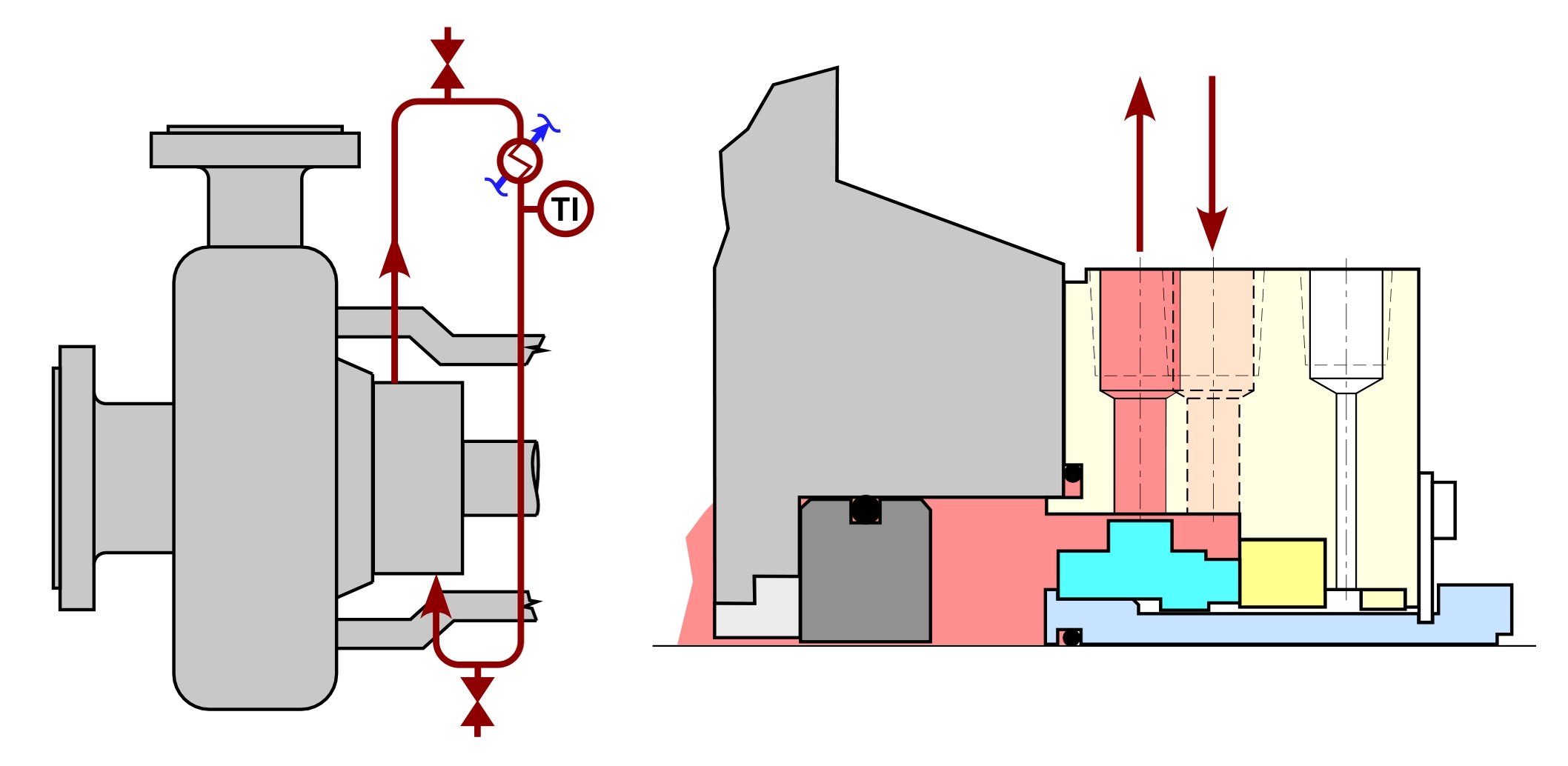
Figure 2 Piping Plan 23
Plan 23 is defined as a circulation of process fluid from the seal chamber, through a seal cooler, back into the seal chamber. A bushing is required in the back of the seal chamber to minimize the interchange of the lower temperature process fluid in the seal chamber and the higher temperature fluid in the pump casing.
Pros
Since the cooled fluid is recirculated in the piping plan and not lost back into the pump, the Plan 23 can more easily create a lower temperature environment in the seal chamber. The seal cooler primarily removes heat entering the seal chamber from seal generated heat and heat soak through the pump casing. This is significantly less than the heat loads in a Plan 21 resulting not only in lower seal chamber temperatures but also a lower heat loss from the pump and process.
The lower heat loads in a Plan 23 can create additional benefits. The lower cooling capacity requirements can allow for smaller seal coolers to be selected and have reduced cooling water requirements. The lower operating temperatures in the piping plan also reduces the potential for fouling in the seal cooler.
Cons
Fluid circulation in a Plan 23 is created by a pumping device on the rotating seal. While these pumping devices (or pumping rings) can create flow, they cannot overcome significant friction losses in the piping system. For this reason, the system is designed with features such as large diameter tubing, a minimum number of fittings, smooth bends, and short piping runs.
A Plan 23 is also a “closed” system. Fluid circulates around from the seal chamber to the seal cooler and back without a natural means for venting gases or vapor from the system. All Plan 23s must be designed with a high point vent (or vents) to fully remove all vapor from the seal chamber, piping, and seal cooler prior to operation. Processes fluids which continually produce vapors may require additional periodic venting while the system is in operation.
Common considerations
Thermosyphoning – Fluids at different temperature will have different densities. In a Plan 21 and 23, this can be used to enhance fluid flow. A properly designed system can have this natural flow (or thermosyphoning) add to the pressure or pumping ring induced flow. For this to occur, the seal cooler must be mounted at an elevation slightly higher than the seal. Even when the pump is on standby, thermosyphoning can produce enough fluid flow to lower the seal chamber temperature.
Heat soak – Since the seal chamber is at a temperature lower than the process temperature in the pump, heat will be transferred into the seal chamber. There are design practices which can reduce heat soak. All seal chambers must have an effective bushing at the back of the seal chamber. This will help prevent intermixing of the high and low temperatures fluids in this region. The bushing can also be designed to reduce heat transfer through conduction (by using materials with low thermal conductivity) and convection (by reducing the heat transfer area in the seal chamber). Seal glands can also be designed with thermal breaks to reduce conductive heat transfer.
Seal coolers – Seal coolers can be either water-cooled or air-cooled. While both options could be used in either the Plan 21 or 23, in practice one will generally be a better choice depending on application conditions. In cases where cooling water is not available, the air-cooled seal cooler is the only option. In very high temperature applications with a Plan 21, air-cooled may be a better option since it is not prone to fouling. In moderate temperature applications, water-cooled seal coolers can provide lower temperatures. Water cooling also relies on the cooling water temperature in the plant and therefore provides more stable temperatures than an air-cooled unit relying on ambient temperatures.
Fluid properties – It is common for seal OEMs to perform calculations estimating the steady-state temperatures of a Plan 21 and 23. This is critical for activities such as sizing the seal cooler or defining cooling water requirements. It is less common for seal OEMs and end users to consider off-design
application conditions such as standby. For example, if a pump with an air-cooled Plan 23 is on standby in the middle of winter, will the process fluid solidify in the cooler or will the Plan 23 be able to re-establish circulation once the pump is restarted. It is critical to consider all potential application conditions in the analysis.
Recommendations
When it is necessary to reduce the temperature in the seal chamber, either piping plan may be applied. In most cases, a Plan 23 will provide the most effective and efficient cooling and would be the first choice. Water-cooled seal coolers also are more effective and will provide more stable operating conditions for the seal. There are however applications where a Plan 21 or an air-cooled seal cooler would be more beneficial. The end user should consult their seal OEMs to properly engineer a system for their specific conditions.
https://empoweringpumps.com/flowserve-sealing-tips-proper-filling-of-plan-53c-systems/


Comments