The use of variable frequency drives (VFDs) for motor control continues to grow year over year. VFDs allow AC motors to run at different speeds to meet the specific application requirements for driving a load. The fundamental purpose of using a VFD can be divided into two categories: 1) process control, and 2) energy savings. Process control is where the speed of a motor is adjusted to better meet the requirements of the driven load, such as a conveyor. In the example of a conveyor the speed is adjusted to meet the process requirements for whatever material the conveyor is transporting. Conveyors are classified as a constant torque load: the amount of torque required to drive the load remains constant across the speed range. The use of VFDs in constant torque applications can optimize process control, but they won’t necessarily save energy.
The second reason to use a VFD, energy savings, applies to what are commonly referred to as variable torque loads. Variable torque loads include applications such as fans and centrifugal pumps. In a variable torque application, the amount of torque required to drive the load varies with speed. In the case of a fan or centrifugal pump, the amount of torque required varies as a function of the square of speed. As an example, if you had a pump running at 1800RPM and you decided to use a VFD to decrease the speed to 1350RPM, the required torque would be (1350/1800)^2, or 0.563 x the torque required to run at 1800RPM. In this example, we reduced the speed by 25% but the required torque dropped nearly 50%. Power varies as a function of the cube of speed, so if we apply this relationship to the above example we get (1350/1800)^3, or 0.422 x the power required at 1800RPMs. For a 25% reduction in speed, we see a nearly 60% reduction in required power. If this were a 50HP/1800RPM pump, the pump would only require about 21HP to run at 1350RPM. Actual energy savings can vary due to design differences and the application environment.
The above analysis demonstrates that considerable energy savings can be achieved by reducing the speed of a variable torque load, such as a pump, when full demand is not required. For pumping applications, VFDs can be added to save energy as well as provide or improve existing process control. In the most basic VFD installation the drive requires at least two pieces of information: 1) a run command (start/stop) and 2) a speed reference, so the drive knows how fast it should be running the motor. One key consideration for a pumping application is what piece of equipment will be providing these commands. External controls such as a PLC can provide the necessary information for a VFD to run a pump and are often used. VFDs in installations that use external equipment to provide a run command and speed reference can be basic in design and many options are available.
Some advanced VFDs provide intelligent pump control. Unlike a basic VFD, a VFD designed specifically for pumping applications may have provisions to connect an external sensor, such as a pressure transducer, which will provide feedback directly to the drive. In this example, the drive could be configured to run the pump at the speed required to maintain a pressure setpoint without the need for an external PLC or other controller. If water demand increases and pressure drops, the VFD will speed up the pump to meet demand; when demand subsides and pressure increases to or beyond the setpoint the drive will slow the pump down. Figures 1 and 2 illustrate some example setups using an intelligent pump VFD.
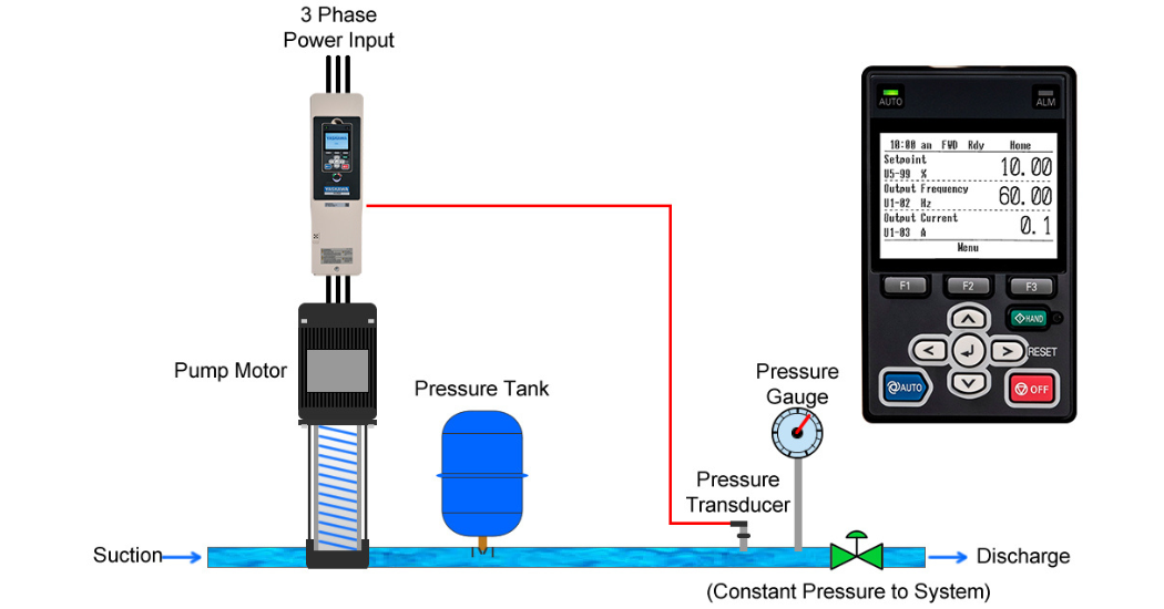
Figure 1: Single drive with a single pump, featuring feedback from a pressure transducer for constant pressure control.
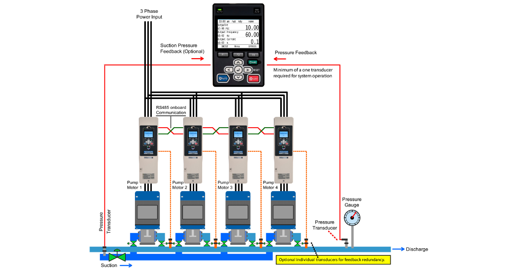
Figure 2: Multiple drive/pump pairs working in parallel. This setup is ideal for applications where there is a wide range of demand.
Advanced VFDs for pumping applications can offer additional parameter settings to specifically tailor the drive and tune it for a specific application. Some key features to look for are:
- Dry well detection: the VFD can detect when the pump has lost prime. The drive will typically stop and indicate a faulted condition to protect the pump.
- Sleep / sleep boost: when the drive meets the pressure setpoint it will typically start slowing down the pump. If pressure is maintained at low pump speeds for an extended period of time the drive will determine that there is little or no demand and enter a “sleep” state. A sleep state is when the drive is stopped but ready to run if pressure drops. Sleep boost is a feature that allows the drive to add some extra pressure to the system before going to sleep which is useful in systems where there
may be small leaks, such as the case of a leaking toilet. Configuring sleep boost will prevent the system from unnecessarily cycling in and out of a sleep condition to maintain pressure when small leaks are present. - Wire break detection: prevents runaway drive operation should the wire to the pressure transducer break.
- Low incoming pressure alarm: for pumps used in booster applications this feature can alert the user to a low municipal water pressure condition.
- Broken pipe / not meeting setpoint detection: this feature allows the drive to be configured to fault or alert the user if the pressure setpoint cannot be reached. This condition can be the result of a catastrophic failure, such as a broken pipe.
- Support for multiple pumps and drives: pumping systems with a wide range of demand can benefit from having multiple pumps working in parallel. In these applications the drives “talk” to each other to coordinate how many pumps are online to meet the demand.
The list of available advanced pumping features is extensive, the above covers a small subset of the capabilities offered by an intelligent pump VFD. Compared to running pump motors direct online at a fixed speed and output, adding a VFD can offer energy savings potential as well as full process control. With a properly selected and configured VFD, customers can enjoy a better user experience while saving money on energy costs.