An MCRT® torquemeter must be installed properly as an integral part of a drive line network in order to achieve satisfactory operation. Proper installation will: a) transmit the desired torque load, b) compensate for misalignments in drive line components, and c) not introduce undesirable loading into the torquemeter shaft.
Optimum installation must therefore address several key areas: shaft misalignments, coupling types, and torquemeter mountings. This article discusses each of these areas, plus some additional considerations and diagrams of correct and incorrect installations.
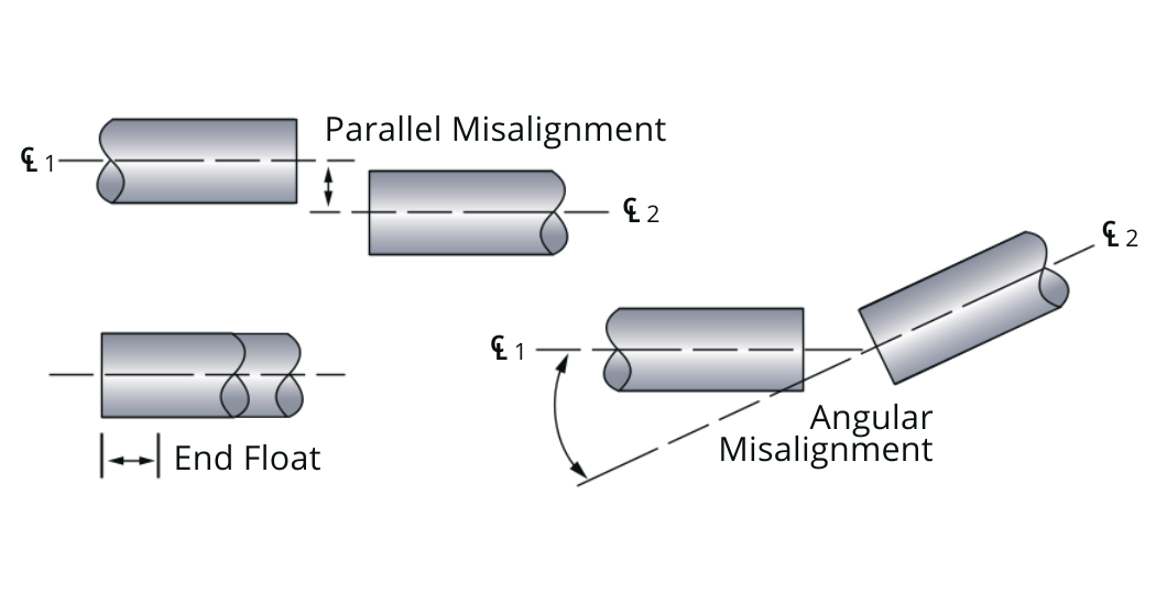
Drive line component mechanical tolerances will always cause misalignments between the ends of coupled shafts. The misalignment(s) that occur include parallel, angular, and end float. They can and will exist in any combination. Figure 1 illustrates each form of misalignment.
Flexible shaft couplings are used to accommodate these misalignments and to transmit the desired torque. The coupling manufacturer will state both the coupling’s torque capacity and misalignment capabilities.