The connection between suction specific speed Sw (NSS)and minimum flow (Qmin) is that, in general, a higher value of Sw (NSS) is associated with a higher value of Qmin. Beyond that generalized statement, however, there is wide range of deviation and exception.
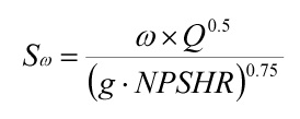
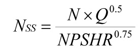
For rotodynamic (centrifugal, mixed-flow and axial flow) pumps suction specific speed is the main suction performance parameter. As a refresher, the two commonly used equations for Sw and NSS are as follows.
The non-dimensional version – the one that ideally we would all be using – is:
The customary version – the one with various unit conventions in use – is:
In the above equations, Q is the flow per eye of the first stage impeller. The equation for Sw requires consistent units and the resulting value is dimensionless. The equation for NSS is based on customary units and its resulting value is not strictly dimensionless, but is used as an index of suction performance capability.
The minimum flow value is not strictly defined by a single equation. From a vibration standpoint, minimum flow may be evaluated as the product of the onset of suction recirculation (QSR), and factors for speed and flow (K1), specific gravity (K2), NPSH margin ratio (K3), intermittency of operation (K4) and mechanical design margin (K5). The equation [1] is:
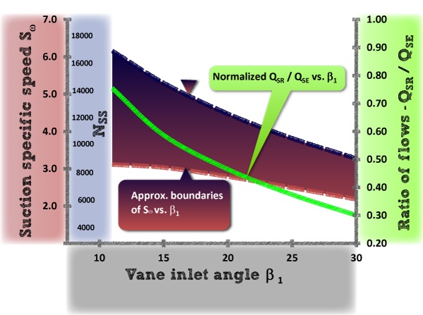
The onset of suction recirculation (QSR) is approximated by the product of rotational frequency (w), impeller eye diameter (D1), and eye and vane geometry factors, including the inlet vane angle (b1). The linkage between QSR and Sw is inlet vane angle b1 as detailed in reference [1]. Chart A graphically shows this connection. QSR tends to increase with increasing Sw(NSS) or decreasing b1. A wide range of suction specific speeds is possible for a given impeller vane inlet angle. The range of variation in the theoretical curve for the ratio of QSR/QSE (where the QSE in the denominator is the shockless entry flow) is difficult to forecast due to inlet and impeller suction geometry details which cannot be readily included in one-dimensional equations.
The factors representing pump hydraulic forces are K1 and K2. These forces are roughly proportional to the product of rotational speed (N), flow (Q) and specific gravity (SG). The speed of a given machine and its size in terms of volume rate of flow are prominent factors in establishing the severity and range of minimum flow operation.
Take, for instance, a nominal 2 x 1.5 ANSI (ASME B73.1) pump at 3500 rpm with a relatively high suction specific speed of 5.1 (14,000 US). The minimum continuous flow is relatively low, 20% of best efficiency point flow (QBEP) flow pumping cold water. In this case, a high Sw (NSS) and a correspondingly high value for QSR is offset by a low value for the product of factors K1and K2 representing hydraulic forces.
A high pressure 8 x 10 boiler feed pump operating at 5500 rpm with a moderate suction specific speed of 3.2 (8,800 US) has a minimum flow of 55% of QBEP, pumping hot boiler feed water. Large high energy pumps tend to require higher minimum flow limits primarily due to the effects of size and speed.
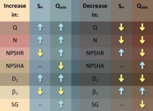
The general trends of increasing or decreasing values of key variables in relationship to Sw (NSS) and Qmin is shown in Table A. Note that the effects on Sw (NSS) and Qmin due to a change in NPSHR are opposite. A reduced level of NPSHR for a given NPSHA will increase the NPSH margin ratio, tending to suppress cavitation. This reinforces the notion that Sw (NSS) and Qminare substantially independent.
Table A – General effect of suction specific speed and minimum flow variables
For some multi-stage pump applications involving a relatively low value of the NPSH Margin ratio, minimum flow is governed by temperature rise to avoid flashing in the balance line return to suction. In this case minimum flow is determined by factors other than suction specific speed. And there are other factors for specific pumping applications that can affect minimum flow, one being the rate of cavitation erosion damage.
In summary, while suction specific speed Sw (NSS) can be related to the onset of suction recirculation flow QSR, the linkage to a practical value for minimum continuous flow Qmin requires additional factors. A principal factor affecting minimum continuous flow, for vibration purposes, is the energy level of the machine, but other factors such as the NPSH margin ratio are important.
For an independent evaluation of factors affecting pump operation at off-peak conditions, contact an experienced consulting engineer who can help with your specific application.
Tags: suction specific speed, minimum flow, minimum continuous flow, onset of suction recirculation, vane inlet angle, impeller eye diameter, suction performance
[1] S. Gopalakrishnan’s paper titled, “A New Method for Computing Minimum Flow,” Proceedings of the Fifth International Pump Users Symposium; Texas A&M University, May 1988, pp. 41-47.

