A common issue in the case of electrically driven submersible pumps, in particular for the construction industry and remote locations, is operational problems and winding failure due to undervoltage. This occurs in applications that require extraordinarily long cables, as well as supply cabling/power lines up to the starter. The problem is called ‘voltage drop’ – a condition where a portion of the supply voltage is lost within the cable itself.
An electric motor is designed to operate in power conditions related to voltage supply. For instance, it should be designed ot operate in an extreme of +/-10% of nameplate voltage and no more than 5% voltage unbalance. Optimal performance is less than +/-5% of nameplate voltage and under 2% voltage unbalance. While unbalance will be covered under a future article, voltage drop relates directly to the nameplate.
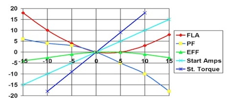
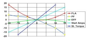
Figure 1: Effect of Voltage Variation From Nameplate (NEMA MG1-2010)
As noted in Figure 1, variations from the nameplate voltage impact the operation of the motor and, as a result, the pump. When conditions are noted upon application, such as high amps or low flow, under-voltage conditions should be considered.
Calculating the voltage drop and effects is relatively straight forward and requires just a little information:
a) Supply voltage;
b) Ambient Temperature (i.e.: water temperature);
c) Operating current;
d) Cable size and type (single or three phase);
e) Length of cable run; and,
f) Copy of NEC Chapter 9, Table 8.
It should be noted that the voltage drop is a direct result of power loss in the cable known as I2R losses. These losses are observed in the form of heat, so a high voltage drop can also result in a higher cable temperature. This can cause degradation in the cable insulation system and increases the voltage drop problem as increasing temperature increases cable resistance increases voltage drop, etc. The supply voltage at the controls minus the voltage drop is what the motor sees at the pump.
There are two basic formulae for calculating voltage drop. One is for single phase applications and the second is for three phase applications.
Equation 1: Single Phase Voltage Drop Equation
Equation 2: Three Phase Voltage Drop Equation
The R is the ohms per foot of cable, the L is length in feet of cable, and I is the current of the application. The NEC Chapter 9, Table 8 is based on 75oC cable temperature. The actual resistance of the cable can be adjusted to the ambient temperature using Equation 3.
Equation 3: Adjusting Resistance for Temperature
With á¼ï¿½ is 0.00323 for Copper and 0.00330 for Aluminum Conductors
So, let’s apply the example to one application using a 460 Volt pump with a supply voltage of 465 Volts. The cable is 14/3 cable for a length of 250 feet, the ambient temperature is 30oC water, and the operating current is 15 Amps. Per the NEC table, the stranded cable has a resistance of 3.26 ohms per kft, or 0.00326 ohms per foot.
The resistance would be adjusted as follows:
Example 1: Adjusting Resistance for Temperature
0.00326 Ohms/ft*[1+0.00323(30C-75C)] = 0.00279 Ohms/ft
Now we add this information to the voltage drop formula for three phase:
Example 2: Calculating Voltage Drop Across the Cable
1.73*0.00279Ohms/ft*250ft*15Amps = 18Volts
The percentage of voltage drop would be (18V/465V)*100% = 3.9%.
It is also recommended that voltage drop remain under 3% and 6% in worst-case instances to prevent excess heating of the cable. The heating effect, or I2R, would be measured in Watts as shown in Equation 4 and Example 3.
Equation 4: Power Loss
Watts = I2 * R
Example 3: Power Loss from Example 2
152Amps * (250ft * 0.00279Ohms/ft) = 157 Watts
This means that (157W/746W/hp), or 0.21 hp, is lost to heating the 250ft of cable. Even though the effect is minimal on operation of the motor due to an undervoltage of (465V – 18V =) 447 Volts, which would be an undervoltage of (((460V-447V)/460V)*100% =) 2.8%, the loss of 3.9% would recommend the next size cable, or 12/3.
A single phase system is handled in a similar manner. Using the same ambient temperature as in the first examples, 14/2 cable, 250 ft, nameplate voltage of 230V, supply voltage at 230V at the starter, and running current of 29Amps. The voltage drop would be as shown in Example 4.
Example 4: Voltage Drop in Single Phase Application
2*0.00279Ohms/ft*250ft*29Amps = 40.5Volts
In this case, the power loss is 587Watts, or 0.79hp, in the cable, the voltage at the motor and undervoltage are both 189.5 Volts and 17.6%. The result is a needed change in cabling and recalculation of voltage drop with the new wire size. Operating the submersible pump in this condition would cause the winding to fail rapidly.
It is possible to calculate total voltage drop if two wire sizes are used (larger cable extension to the submersible pump cable) by calculating each length separately and adding them together.


