If a wide receiver has the right speed and good hands, all that‘s needed from the quarter-back is to throw the ball accurately and they‘ll probably finish up with some good yardage and maybe even a touch-down. Believe it or not, much the same is true of a pump and it‘s suction conditions. If the pump has the right speed and is the right size, all that‘s required from the “quarter-back” is to deliver the liquid at the right pressure and with an even laminar flow into the eye of the impeller. If the quarter-back‘s pass is off target, badly timed, or the balls turning end over end in the air, the receiver may not be able to hold on to it and there‘s no gain on the play.
When that happens, the quarter-back knows he didn‘t throw it properly and doesn‘t blame the receiver. Unfortunately, that‘s where the comparison ends. The engineering “quarter-backs” tend to blame the pump even when its their delivery that‘s bad !!
Just as there are specific techniques a quarter-back must learn in order to throw accurately, so are there certain rules which will ensure the liquid arrives at the impeller eye with the right pressure and the even laminar flow necessary for reliable operation.
Rule #1. Provide Sufficient NPSH
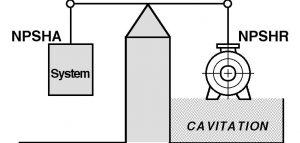
Without getting too complicated on a subject about which complete books have been written, let‘s just accept the basic premise that every impeller requires a minimum amount of pressure energy in the liquid being supplied in order to provide adequate performance without cavitation difficulties. This pressure energy is referred to as Net Positive Suction Head.
The NPSH is supplied from the system and is solely a function of the system design on the suction side of the pump. Consequently it‘s controlled by the system designer.
To avoid Cavitation, the NPSH available from the system must be greater than the NPSH required by the pump, and the biggest mistake that can be made by a system designer is to succumb to the temptation to provide only the minimum required at the rated design point. This leaves no margin for error on the part of the designer, or the pump, or the system and has proved to be a costly mistake on many occasions.
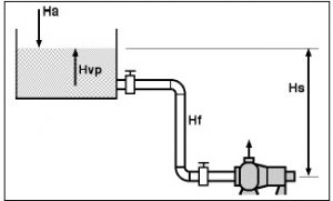
Figure 1
In the simple system as shown in Fig. 1., the NPSH Available can be calculated as follows:-
NPSHA = Ha + Hs – Hvp – Hf
where, Ha = The head on the surface of the liquid in the tank. In an open system like this, it will be atmospheric pressure.
Hs = The vertical distance of the free surface of the liquid above the centre-line of the pump impeller. If the liquid is below the pump, this becomes a negative value.
Hvp = The vapour pressure of the liquid at the pumping temperature expressed in feet of head.
Hf = The friction losses in the suction piping.
The NPSH Available may also be determined with the following equation:-
NPSHA = Ha + Hg + V2/2g – Hvp
where, Ha = Atmospheric pressure in feet of head.
Hg = The guage pressure at the suction flange in feet of head.
V2
—- = The velocity head at the point of measurement of Hg.(Guage readings do not include velocity head.)
2g
Rule #2. Reduce the Friction Losses
When a pump is taking it‘s suction from a tank, the pump should be located as close to that tank as possible in order to reduce the effect of friction losses on the NPSH available. This is usually accomplished by using a larger diameter line to limit the linear velocity to a level appropriate to the particular liquid being pumped. Many industries work with a maximum velocity of approximately 5 ft./sec., but this is not always acceptable.
When considering the proximity of the pump to the tank it is also imperative that it be far enough away to ensure that correct piping practice can be followed.
Rule #3. No Elbows on the Suction Flange
Much discussion has taken place over the acceptable configuration of an elbow on the suction flange of a pump. Let‘s simplify it. There isn‘t one !
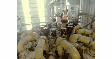
There is always an uneven flow in an elbow and, when one is installed on the suction of any pump, it introduces that uneven flow into the eye of the impeller. This can create turbulence and air entrainment which can result in impeller damage and vibration.
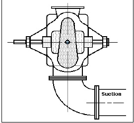
When the elbow is installed in a horizontal plane on the inlet of a double suction pump, uneven flows are introduced into the opposing eyes of the impeller and essentially destroy the hydraulic balance of the rotating element. Under these conditions the overloaded bearing will fail prematurely and regularly if the pump is packed. If the pump is fitted with mechanical seals, the seal will usually fail instead of the bearing, but just as regularly and often more frequently.
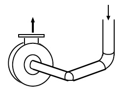
The only thing worse than one elbow on the suction of a pump is two elbows on the suction of a pump – particularly if they are positioned in planes at right angles to each other. This creates a spinning effect in the liquid which is carried into the impeller and causes turbulence, inefficiency and vibration.
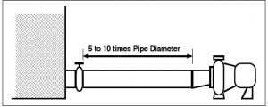
A well established and effective method of ensuring a laminar flow to the eye of the impeller is to provide the suction of the pump with a straight run of pipe in a length equivalent to 5 to 10 times the diameter of that pipe. The smaller multiplier would be used on the larger pipe diameters and vice versa.
Rule #4. Stop Air or Vapour Entering the Suction Line
Any high spot in the suction line can become filled with air or vapour which, if transported into the eye of the impeller, will create an effect similar to cavitation and with the same results. Services which are particularly susceptible to this situation are those where the pumpage contains a significant amount of entrained air or vapour, as well as those operating on a suction lift, where it can also cause the pump to lose it‘s prime.
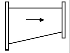
A similar effect can be caused by a concentric reducer. The suction of a pump should be fitted with an eccentric reducer positioned with the flat side uppermost as shown in Fig. 6.
If a pump is taking its suction from a sump or tank, the formation of vortices can draw air into the suction line. This can usually be prevented by providing sufficient submergence of liquid over the suction opening, and a bell-mouth design on the opening will reduce the amount of submergence required. This submergence is completely independent of the NPSH required by the pump. It is worthwhile noting that these vortices are more difficult to trouble-shoot in a closed tank simply because they can‘t be seen as easily.Great care should be taken in the design of a sump to ensure that any liquid emptying into the sump does so in such a manner that air entrained in the inflow does not pass into the suction opening. Any problem of this nature may require a change in the relative positions of the inflow and outlet if the sump is large enough, or the use of baffles.
Rule #5. Correct Piping Alignment
Piping flanges must be accurately aligned before the bolts are tightened and all piping, valves and associated fittings should be independently supported without any strain being imposed on the pump. Any stresses imposed on the pump casing by the piping reduces the probability of satisfactory performance.
Under certain conditions the pump manufacturer may identify some maximum levels of forces and moments which may be acceptable on the pump flanges.
In high temperature applications, some piping misalignment is inevitable owing to thermal growth during the operating cycle. Under these conditions, thermal expansion joints are often introduced to avoid transmitting any piping strains to the pump. However, if the end of the expansion joint closest to the pump is not anchored securely, the object of the excercise is defeated as the piping strains are simply passed through to the pump.
Rule #6. When Rules 1 to 5 have been ignored, follow Rules 1 to 5.
Piping design is one area where the basic principles involved are regularly ignored resulting in problems such as hydraulic instabilities in the impeller which translate into additional shaft loading, higher vibration levels and premature failure of the seal or bearings. As there are many other reasons why pumps could vibrate, and why seals and bearings fail, the trouble is rarely traced to incorrect piping.
It has been argued that, because many pumps are piped incorrectly and most of them are operating quite satisfactorily, piping procedure is not important. Unfortunately, satisfactory operation is a relative term and what may be acceptable in one plant, may be totally inappropriate in another. It should also be noted that the piping system is rarely placed under scrutiny as a problem source when trouble-shooting a pump failure.
Even when ‘satisfactory’ pump operation is obtained, that doesn‘t automatically make a questionable piping practice correct, it merely makes it lucky.
The suction side of a pump is much more important than the piping on the discharge. If any mistakes are made on the discharge side, they can usually be accommodated by increasing the performance capability from the pump. Problems on the suction side however, can be the source of ongoing and expensive difficulties which may never be traced back to that area.
In other words, if your “receivers” aren‘t performing well, is it their fault ?
Or does the “quarter-back” need more training ?
About the Author
Ross Mackay is an internationally renowned expert in pumping reliability. He specializes in helping companies increase their pump asset reliability and reduce operating and maintenance costs through pump training programs. He is the author of “The Practical Pumping Handbook”, and “The Mackay Self-Directed Pump Reliability Training System”. He can be reached at 1-800-465-6260 or by visiting
www.practicalpumping.com

