Author: Abby Zimmerman, Applied Flow Technology
Heat exchangers are some of the most expensive pieces of process equipment, so it is crucial that their pressure losses and heat transfer are well understood. AFT Fathom and AFT Arrow allow users to model heat exchangers within their piping systems. Pressure loss models include input K factors, resistance curves, or tube bundle information. When energy balances are being considered, users can choose between 11 heat transfer models in AFT Fathom and 12 heat transfer models in AFT Arrow to best meet their hydraulic modeling needs.
While AFT Fathom and AFT Arrow can also model heat transfer in pipes, this blog will focus on the thermal models available for heat exchangers. The NTU-Effectiveness method is used to perform the energy balance for heat exchangers with these configurations:
- Parallel Flow
- Counterflow
- Crossflow
Parallel Flow: The parallel flow model can be used when both fluids enter at the same end of the heat exchanger and exit at the same end of the heat exchanger. A heat exchanger with parallel flow has a large temperature difference between the two fluids at the entrance. As the fluids travel in parallel flow, however, this difference decreases as the fluid temperatures approach each other.
Counterflow: A counterflow heat exchanger is the inverse of a parallel flow heat exchanger. The hot fluid enters at one end, while the cold fluid enters at the other end. Counterflow is the most common type of heat exchanger when both fluids are liquids.
Crossflow: A crossflow heat exchanger is most commonly used in gas heating or cooling. The secondary fluid flows across tubes carrying the system fluid, as shown in Figure 1 above. There are three types of crossflow heat transfer models available in AFT Fathom and AFT Arrow: both fluids unmixed, system fluid mixed, and secondary fluid mixed.
The NTU-Effectiveness method is used when the fluid inlet and outlet temperatures for the heat exchanger are not known. We will review the NTU-Effectiveness method here to gain a better understanding of what AFT Fathom and AFT Arrow are doing when you choose a thermal model for your heat exchanger.
To start, the NTU-Effectiveness method requires that the maximum possible heat transfer be found. Theoretically, the maximum heat transfer would occur in a counterflow heat exchanger of an infinite length. In this scenario, the maximum possible temperature difference is the difference between the inlet temperature of the hot fluid and the inlet temperature of the cold fluid:
Eq. 1) Th1 – Tc1
The minimum heat capacity rate can then be found by multiplying the mass flow rate by the specific heat for the hot fluid and the cold fluid:
Eq. 2) Ch = (ṁcp)h
Cc = (ṁcp)c
and Cmin = the lower value
The fluid with the higher heat capacity rate changes temperature more quickly along the length of the heat exchanger, but the fluid with the lower heat capacity rate actually sees the maximum possible temperature change. Based on this, the maximum heat transfer between the two fluids in the theoretical heat exchanger is the minimum heat capacity rate multiplied by the maximum temperature difference:
Eq. 3) qmax = Cmin(Th1 – Tc1)
The effectiveness of a heat exchanger is the ratio between the actual heat transfer rate and the maximum possible heat transfer rate:
Eq. 4) ε = q/qmax where q = Ch(Th1 – Th2) = Cc(Tc2 – Tc1)
If the effectiveness and the inlet conditions are known, the amount of heat transferred between the two fluids can be calculated without knowing anything about either fluid’s outlet temperature:
Eq. 5) q = εCmin(Th1 – Tc1)
The key to the NTU method becomes calculating the effectiveness, which is a function of the heat capacity ratio, C, and the number of transfer units, NTU:
Eq. 6) C = Cmin/Cmax
Eq. 7) NTU = N = UA/Cmin where U is the overall heat transfer coefficient and A is the heat transfer area
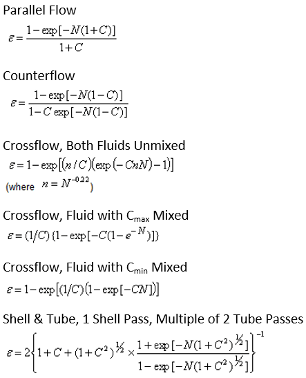
Each heat exchanger configuration has a unique relation used to calculate the effectiveness. These become the fundamental equations for the six thermal models that we discussed previously and can be seen in Figure 2 below.
The other thermal models available in AFT Fathom and AFT Arrow do not need to use the NTU-Effectiveness method because they directly specify information about the heat exchanger outlet conditions. They are:
- Controlled Downstream Temperature
- Controlled Downstream Temperature (Stagnation)
- available in AFT Arrow only
- Enthalpy Stagnation Rise
- Temperature Stagnation Rise
- Specified Heat Rate In Constant
- Specified Heat Rate In vs. Flow
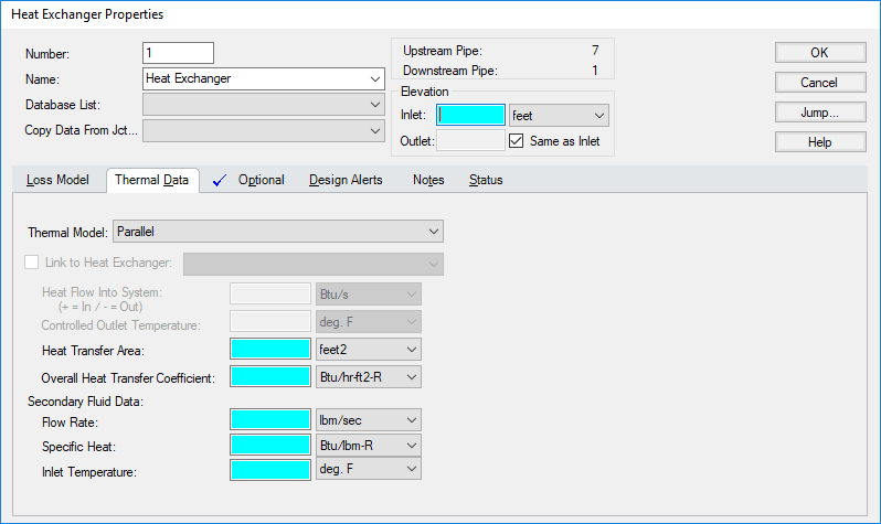
Now that a basic understanding of each thermal model has been established, we will look at a comparison of the heat transfer results between the different thermal models that use the NTU-Effectiveness method. The input needed for all six of these thermal models is the same and is shown below in Figure 3.
When identical Thermal Data is input into the heat exchanger, but the Thermal Model is varied, these are the results:
According to the NTU-Effectiveness method, AFT Fathom calculates that a counterflow heat exchanger will cool the hot liquid the most, while a parallel flow heat exchanger will cool the hot liquid the least. When using a single heat exchanger junction, like in this example, notice that you must specify the Secondary Fluid Data (shown in Figure 3) because only the primary fluid loop is modeled.
If you would like AFT Fathom or AFT Arrow to calculate this Secondary Fluid Data, you will need to model both the hot fluid side and the cold fluid side of the heat exchanger. The feature that allows you to do this is called Thermal Linking and is available for the six NTU-Effectiveness thermal models.
Thermal Linking allows two heat exchangers to represent two sides of the same heat exchanger. This capability can also be used to model heat transfer loops with different fluids. For more information on how to use Thermal Linking, please refer to this article: Modeling Tube Side and Shell Side of a Heat Exchanger.
Overall, heat transfer modeling for heat exchangers in AFT Fathom and AFT Arrow is a very powerful tool. The 11 or 12 thermal models available for heat exchangers allow you to model a variety of configurations. When the output conditions of the heat exchanger are not known, AFT Fathom and AFT Arrow can use the NTU-Effectiveness method to calculate the heat transfer. For information about modeling heat transfer in pipes, check out Erin’s blog!
[1] Cengel, Y. A., Turner, R. H., Cimbala, J. M. (2012) Fundamentals of Thermal-fluid Sciences, 4th edition, London: McGraw Hill Higher Education
How to Model a Tube Rupture in a Heat Exchanger – Webinar on 6/20/18
Learn how to dynamically model a tube rupture in your heat exchanger. Tube ruptures must be evaluated and addressed in order to ensure continued safe operations. Using a model and simulation process is extremely beneficial and can help ensure more accurate sizing and hazard assessments.

![Figure 1: Different Types of Crossflow in a Heat Exchanger [1]](https://empoweringpumps.com/wp-content/uploads/2018/06/aft-fig1-heat-exchanger.png)


