How an existing pump was repurposed as a “new” pump in a new system.
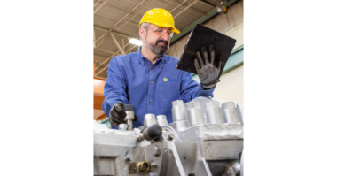
Steve Navarro and Christen Mancini of Hydro Inc.
A pipeline company wanted to extend a transport line and improve its efficiency. The line required the use of drag reducing agent (DRA) to operate in high flow conditions. Using DRA added to the operation costs, and the operator had limited ability to transport the desired quantity of fuels even with the use of the DRA.
Instead of purchasing new equipment, the pipeline company decided to repurpose an existing pump. For several years a two-stage pump lay idle in storage at an offsite facility. A pump service center near Atlanta, USA determined that the pump could suit the new operating conditions through a hydraulic
modification. By using this solution, the pipeline company reduced equipment lead time and cost, developed extended hydraulics that met the design conditions, obtained optimal efficiency, met government regulations, and acted sustainably.
The user partnered with Hydro Inc to provide total support in executing this solution by designing new impellers and modifying the casing volute; providing certified performance testing of various impeller diameters; hydrostatically pressure testing the casing; designing a baseplate and assisting with baseplate installation; performing pump and motor alignment; and fitting new coupling assemblies to the equipment.
Challenging requirements
The pipeline company identified two new high flow rate operating points that needed to be met. When the system operates with a booster pump supplying pressure to the mainline pump, the higher flow rate can be achieved; at other times, reduced pressures occur within the pipeline and the mainline pump operates at second, lower flow rate. An additional challenge of horsepower and physical size limitations was imposed by the end user’s desire to use an existing motor with the redesigned pump.

Machining casing volute passage.
The original design point of the pump was 3150 gallons per minute (GPM) at 1170 feet of head pressure; the new operating requirements were 2800 GPM at 1100 feet of head and 3800 GPM at 870 feet of head. The higher of these two flow rates was not achievable with the original pump impellers as it extended far to the right of the best efficiency point in an unstable region of the curve. New hydraulics would achieve the higher flow near the best efficiency point without increasing the pump horsepower, allowing confident use of the existing 1000 horsepower motor. Performance testing to validate new hydraulic design. Machining casing volute passage.
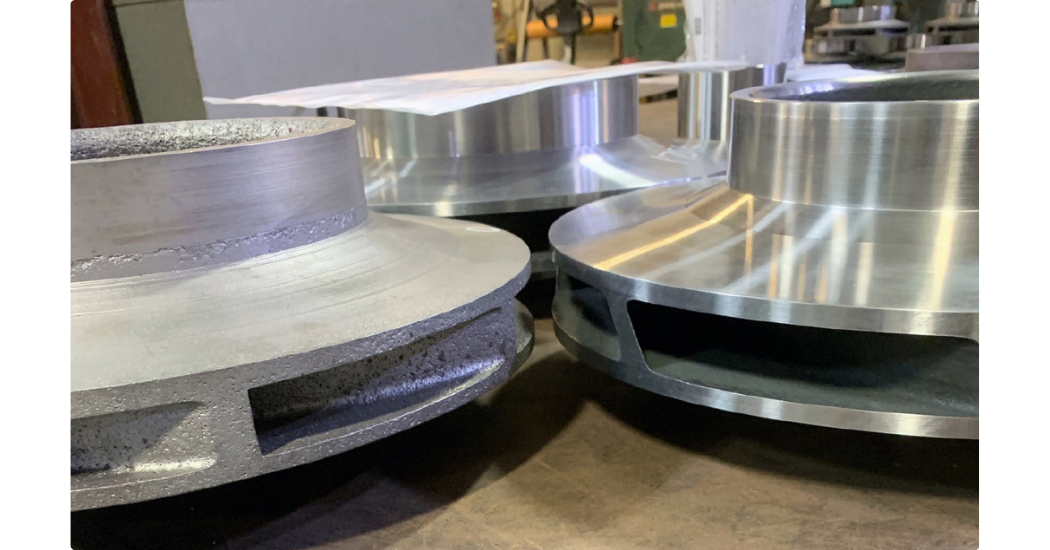
Original impeller (left), new impeller (right) with increased passage width.
The last challenge in repurposing the available pump was the absence of a baseplate. A new baseplate needed to be designed, manufactured, and installed at the new operating location as part of the project.
Development and implementation
The hydraulic modification project was managed through Hydro’s service center in Atlanta. The project took advantage of the capabilities of several other divisions, while also collaborating with the end user to support design changes and testing.
The Global Engineering division designed the new impellers using their expertise in hydraulic design and computational fluid dynamics (CFD). The two new impellers featured increased passage width and extended the maximum impeller diameter from 14.50” to 14.97” to increase the flow rate. After the design was completed, the impellers were manufactured through Hydro’s dedicated parts division to maintain control of component quality and lead time. A spare element was also manufactured with uncut impellers to allow for future flow increases.
In tandem with the new impeller design, the casing volute passages required increased volume to allow for more flow. Templates were fitted to the original raw cast casing, and designers opened the volute passages to achieve a 20% increase in area. The four casing volutes were machined, inspected, and verified in a horizontal milling machine. Machining methods were used to implement this design change, providing better control and precision than handwork.
To design the new baseplate, Hydro’s field reverse engineering team collaborated with the Atlanta service center. After taking dimensions of the installation site, the baseplate was designed from scratch, with an eye for achieving a robust component that would provide a stable foundation for the pump, motor, electrical conduit, and coupling.
Validation through testing
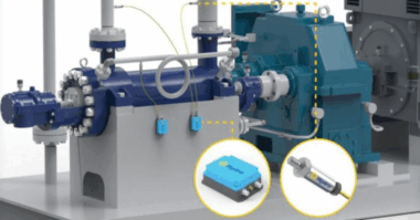
After receiving the new impellers, completing all casing modifications, making new rotor components (shaft, sleeves etc), and completing the hydrostatic testing, the pump was shipped to Hydro’s performance test lab in Chicago. A performance test, net positive suction head required (NPSHr) test, suction pressure test, and resonance test were all performed to verify optimal operation of the equipment.
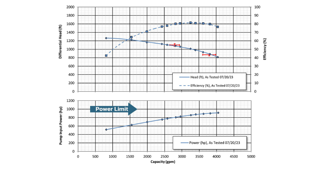
Successfully achieving required operating points and horsepower limits.
The first baseline performance test was run with an impeller diameter of 14.00”, which was ~13.3% larger than the estimated final impeller diameter of 12.35”. This test validated the ability of the design changes to achieve the operating criteria and mitigated the risk of cutting the impellers to the final dimension using only theoretical performance data. With the baseline test completed, the impellers were cut to 12.75” and a second performance test was run.
The second performance test at the 12.75” diameter further validated the theoretical performance information. During this test, inboard bearing temperature and vibration reached abnormal levels. It was determined that the observed conditions were caused by oil characteristics near the upper limits of usability for the ISO 32VG lubricating oil. The oil was changed to an ISO 46VG oil and the test rerun. The pump operated with stable, low temperature bearing behavior. Desiring to proceed cautiously, a resonance test was performed on the bearing housings to identify the natural frequencies of component and ensure that there was adequate separation between these frequencies and any forcing frequencies expected during pump operation.
The impellers were machined to the final diameter of 12.35” for the final test. This test validated the new design operating points were achieved and the horsepower remained below the limit of 1000 horsepower. An additional test was performed with the pump’s inlet suction pressure increased up to 100 psia, simulating field operating conditions when the pump is operated in series with the booster pump. The hydraulic and mechanical performance were both acceptable throughout the 4-hour run time of this test.
Conclusion
After successful performance testing, the pump was returned to the Atlanta service center for painting and delivery to the pipeline site. Service center personnel accompanied the pump to the site to support installation and alignment of the equipment.
This project highlights how existing equipment can be modified to effectively meet new operating conditions or, as in this case, act as a “new” pump in a new system. By leveraging a network of capabilities within a single qualified supplier and engaging in consistent communication, the project was successful. The pipeline team was able to stay up-to-date on the project progress and provide feedback at each milestone; this collaboration and communication were critical elements of the project success.
Originally published in World Pumps Magazine