Pump modifications made to better match the pump to its system result in greater efficiency and reliability – avoiding downtime and unplanned failures.
It’s estimated that 85% of pumps are not optimized to their systems, costing end users both efficiency and reliability. To achieve operational excellence and reduce environmental impact, assessing and improving our systems is essential.
There is a lot of focus on buying new equipment with a higher energy efficiency rating. In reality, the efficiency gains available in optimizing efficiency within the pump design is usually dwarfed by the energy savings available by optimizing the way the pump operates within its system. Not only does optimizing a pump to its system result in a reduction in energy usage, it allows the pump to operate at its best efficiency point (BEP), where reliability is the greatest.
Sometimes pumps and their systems are not matched to operate at the best efficiency flow because of design conservatism on the part of system designers and pump manufacturers. However, many of the systems that are operating off their best efficiency are doing so because changes in the system requirements have occurred over the years without investing in equipment modifications to match this new flow; this is especially true in aging plants that have a higher likelihood of system output or product changes. This was the case at a chemical plant producing ammonia and other nitrogen products for the fertilizer industry.
The plant in question was experiencing recurring reliability problems with their horizontal multistage BB3-style boiler feed pumps. After a series of repeated failures, they decided to partner with Hydro, Inc to perform a failure modes and effects analysis (FMEA) that would diagnose the cause of the failures and provide options for remediation. During the FMEA, a review of the historical system data revealed that an uprate had resulted in a significant change in the way the system needed to be operated.
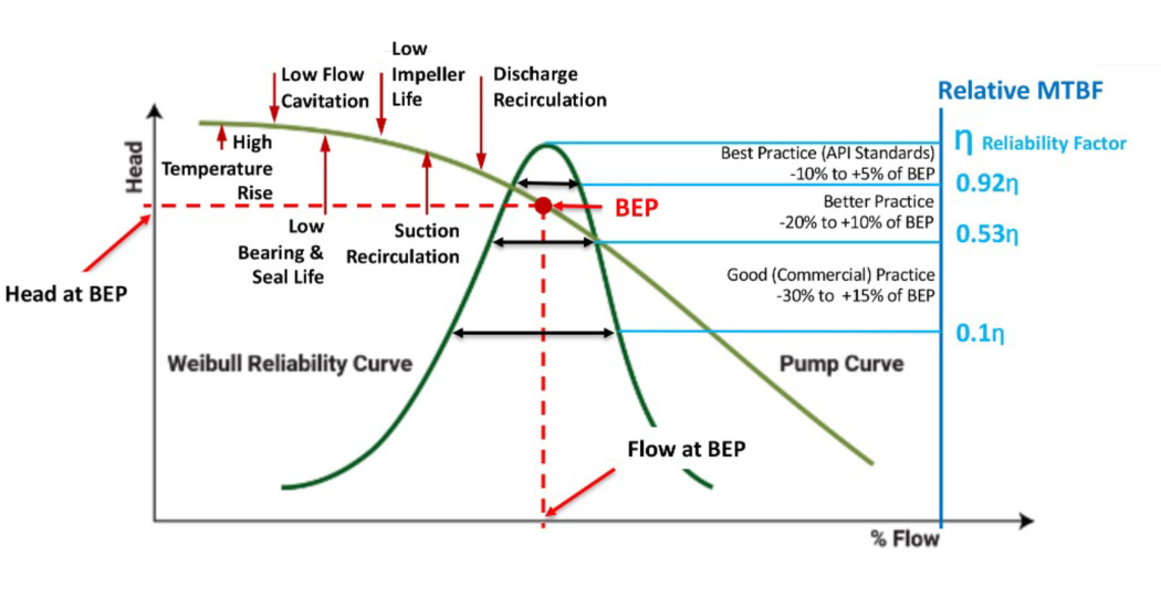
IMAGE 1: Weibull Reliability Curve and Effects of Operation off BEP
Originally, the system had been designed with two 100% pumps installed; this means that only one pump was operated to safely achieve the required system flow rate, with the other pump available as an installed spare. When the total system flow increased, the single pump was no longer able to meet the new flow rate by itself; instead, both pumps needed to operate in parallel to provide the required flow to the system. This new operating condition resulted in each pump running at a flow significantly below the best efficiency point (BEP). Operating away from BEP affects more than required flow to the system. This new operating condition resulted in each pump running at a flow significantly below the best efficiency point (BEP). Operating away from BEP affects more than just efficiency, it also affects the reliability of the equipment.
To better understand why operating two pumps in the uprated system caused them each to run back on their performance curve, we can look at the following simplified example. When pumps operate in parallel, the output of each pump is added to achieve the total system flow. Let’s suppose that the original system was designed to supply 1000gpm with one pump operating at its best efficiency point. The system went through an uprate of 20%, requiring a new flow rate of 1200gpm that the single pump was unable to provide. With two pumps, this new flow rate is evenly split so that each pump supplies 600gpm to the system for a total of 1200gpm. At this flow, they are both operating at 60% of their best efficiency flow, which is far outside of the recommended window of -15%/+10%.
After a comprehensive review, it was determined that hydraulic instability caused by low flow operation was the main cause of the repeated failures. To validate this theory, a disassembly, cleaning, and inspection (DCI) was scheduled to be performed on the next degraded pump that was taken out of service. As expected, the DCI revealed damage indicative of recirculation on the impellers and casing. At the BEP, the angle of the flow matches the angle of the stationary impeller blades and volute cutwaters. As pump operation diverges from the best efficiency flow, the angle of the flow and the blade angle are no longer compatible and the likelihood for fluid recirculation increases. Recirculated flow will cause component damage, localized pressure drops, and decreased rotor stability, resulting in degraded performance and high vibration.
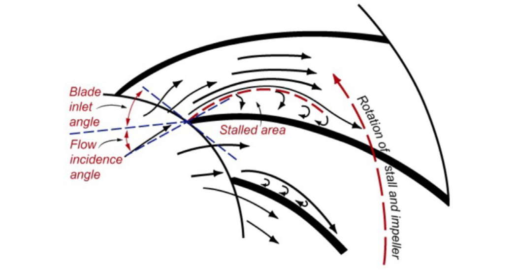
IMAGE 2: Suction Recirculation
With confirmation of the root cause, site engineering and Hydro worked together to develop and implement a solution that would return the system to reliable, efficient operation. While there are many ways to counteract the detrimental effects of fluid recirculation, the best solution is to move operation as close to the BEP as possible.
Two options for pump modifications were put forward for consideration. The first option was to provide new custom hydraulics with performance that matched the new system requirements. This would necessitate the design and manufacturing of new impellers and performance testing. The second option was to perform an underfile modification, where the geometry of the existing impeller is modified to change the performance. Both of these options would return the system to operation with one 100% pump instead of requiring operation with both installed units.
While a hydraulic rerate would allow greater flexibility for future operation changes, the site was concerned about the risk presented by not having a spare onsite for the amount of time necessary to cast and machine new impellers. As such, the customer decided to underfile the existing impellers. When an impeller is underfiled, material is taken away from the underside of the blade at the impeller outlet to increase the impeller passage size. This provides more flow at the same total developed head.
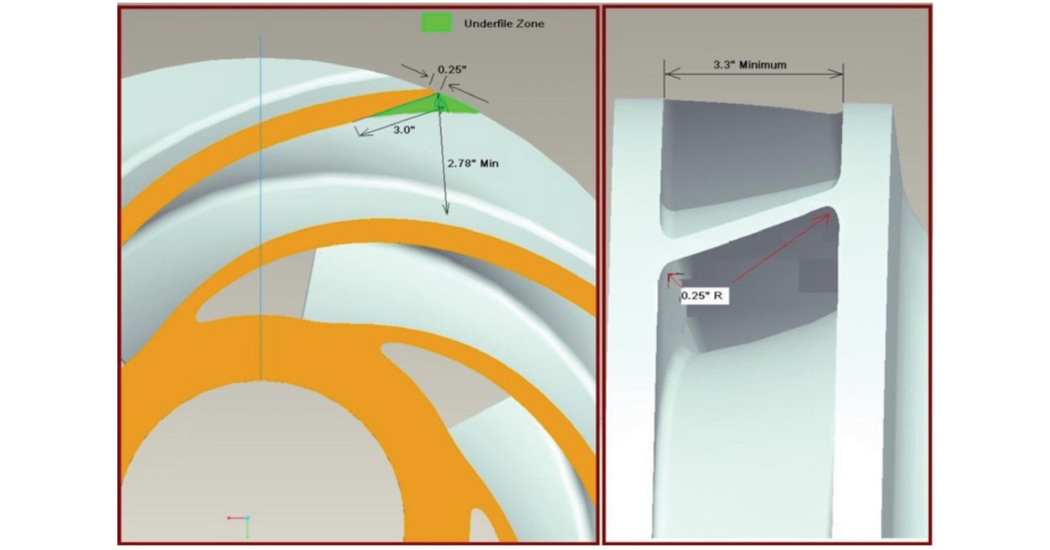
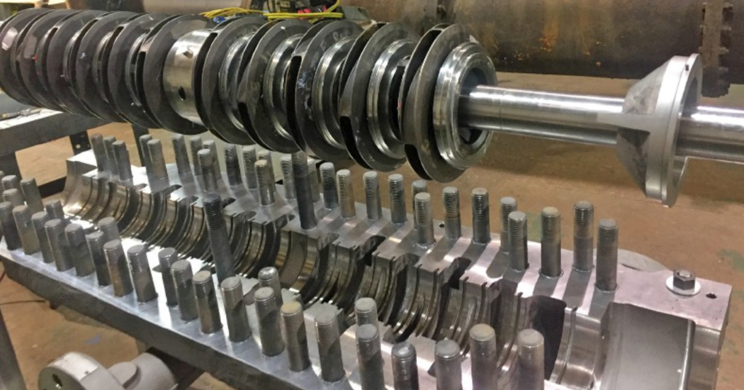
IMAGE 3: Underfile Modification
While it sounds like a simple process, there is a lot of engineering required to successfully complete an underfile modification. A study must be undertaken to determine the appropriate amount to underfile the blade to achieve the required performance. Careful consideration must be made to how much material is removed, as this is a highly stressed area and excessive material loss can weaken the impeller and greatly increase the risk of component failure. Providing the proper geometry where the impeller blade meets the shrouds is also important to minimize the stress concentration factor in this area.
When the modified pump was reinstalled and returned to service, the plant was able to successfully meet the system flow with one pump. The modification has since been completed on the other pump and the spare rotor. All pumps have been running reliably, with lower vibration and no loss of performance that would indicate internal wear.
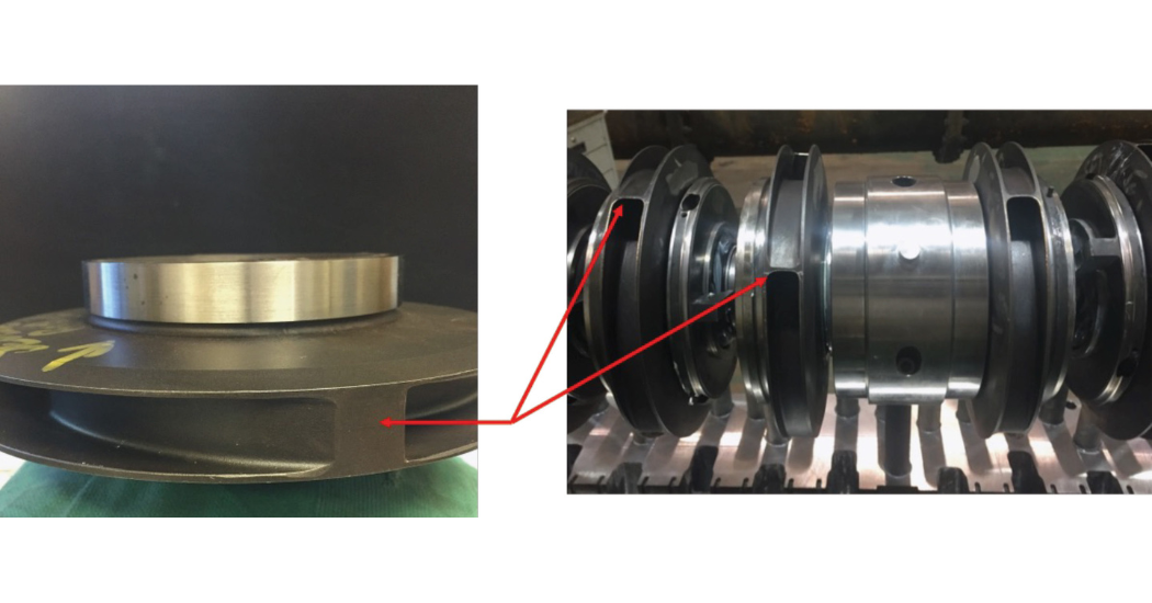
IMAGE 4: Original Impeller with Wide Land (Left) and Underfiled Impeller (Right)
In addition to improving reliability, the modifications made to better match the pump to its system provided several collateral benefits. The site was able to operate with an installed spare once again, reducing any downtime associated with unexpected equipment failure. Operating one pump instead of two and operating at a much greater efficiency has also reduced the horsepower needed to produce the total system flow. This reduces the energy usage of the system, which in turn reduces both the cost to operate the system and the greenhouse gas emissions associated with its operation. As shown in Table 1, operation of the single pump at an improved efficiency will save the site an estimated $74,000/year and 986,000lb/CO2. By taking steps to optimize their pump to its system, the end user was able to mitigate the risk of downtime and loss of production, reduce the total lifecycle costs of their equipment, and support their companies published environmental sustainability goals.