This is the first in a two-part series exploring the selection of valves in solar power applications. The first part will focus on how specially tailored control valves can overcome the challenges inherent in solar power production.
Solar energy is a viable alternative to fossil fuels and nuclear power. It’s safe, climate-friendly and plentiful, especially in the Earth’s sun belt. Technology advancements are bringing down the cost of solar energy production and making mass production more practical than ever before.
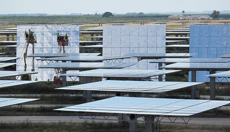
To generate electrical power, concentrated solar power systems use mirrors to focus the sun’s radiation on a receiver, converting it to heat to create steam to drive a turbine. In many solar power systems, concentrated sunlight heats a “transfer fluid,” which can reach temperatures as hot as 300°C (573°F) for synthetic oils and 600°C (1112°F) for molten salts. This fluid can immediately produce steam or store the heat for later use, allowing plants to generate power during periods of peak need or on cloudy days when the sun’s rays are not as abundant.
Concentrated solar power plants are aggressive environments that create challenges for flow management equipment, including:
- High temperatures and drastic temperature changes
- Excessive vibrations due to operating conditions
- Extreme characteristics of the heat transfer fluid
- Aggressive ambient conditions
For example, synthetic oil fluids are prone to leaking; due to its very low viscosity and lubricity, the fluid can cause damage to seals and guiding surfaces at high temperatures, which could result in damage or complete failure of the equipment and lead to productivity losses and plant downtime.
Flow management systems, especially piping system components, must be able to perform reliably within these aggressive environments, including being resistant to thermal shock, corrosion and wear.
Tailored control valves for solar applications
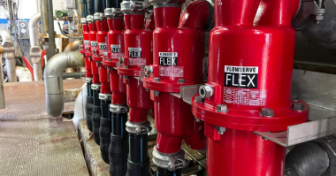
Because of the unfavorable operating conditions in which they operate, control valves have a significant influence on the safety and availability of a solar power plant. Here are a few considerations to keep in mind when evaluating piping system components.
For synthetic oil transfer fluids, a bellows seal with a safety stuffing box is recommended to seal the valve stem. Due to the poor lubricating properties of the fluid, the valve trim must have sufficient wear and galling resistance.
Within molten salt applications, valves are mainly pneumatic operated globe-style or angle-style control valves with buttwelded end connections and extended bonnets. They are welded in line to limit potential leaks. For critical valves, we recommend top-entry design globe-style valves for ease of maintenance. The control valves for molten salts often require unique designs because the fluid is oxidizing, corrosive and often abrasive.
For low difference pressures, specially tailored butterfly valves (e.g., triple eccentric, buttweld ends, extended bonnet, suitable materials) could also be used.
Shut-off valves are often manually operated or equipped with an electric rotary actuator. In molten salt applications, a shroud-less bellows seal design may also be used. Shut-off valves must perform a high number of strokes, and breakage is a risk. Excessive vibrations or oscillations can also reduce the lifespan of a valve. The challenges for the heat tracing of the bonnet are higher, as a possible crystallization of the fluid within the bellows could lead to a failure.
A control valve with a heavy-duty double stem guided plug, seat retainer and clamped seat ring is preferable for molten salt applications due to the comparable low dead space, easily replaceable seat and availability of tailor-made trims.
An extended bonnet is needed to keep the packing temperature within acceptable values, in order to avoid inadmissible exposure of the actuator to high temperatures and allow installation of the heat tracing.
For non-critical operating conditions, up to a differential pressure of 10 bar, parabolic plugs are used. However, for more extreme operating conditions, such as with down-comer or anti-surge valves, multistage valve trims are suitable. Balanced valve trims should not be used due to the risk of the presence of salt crystal formations. A screwed seat ring with metal-to-metal sealing (without a sealing element) is not recommended due to a risk of thread leakage in case of a possible corrosion attack.
The double stem guided, cage-retained design with angle-style valve body and modified seat will allow the piping system to drain in case of a shut-off. To drain the piping system, an angle-type control valve with flow over is required. This valve has a contoured seat designed for flow over for better control at low loads. The seat leakage will remain low over a long period of operation because the sealing area is separated from the vena contracta, and is therefore not exposed to high flow velocity. A multi-step trim will avoid critical operating conditions at high differential pressures.
In the second part in the series, we will examine the materials used in manufacturing valves for solar power applications.


