Author: Dominik Fry, P.E., Engineered Software Inc.
The need for water and wastewater capacity is continually growing on a global scale, and with rising energy costs and a greater emphasis on being green, the users and designers of pumping systems in this industry are realizing the need for more efficient designs and practices. It is estimated that water/wastewater facilities account for 35 percent of typical municipal energy budgets 1. With pumping systems responsible for much of this power consumption, design optimization can result in significant energy savings.
In fact, a considerable number of users, suppliers and designers in all industries, as well as government agencies and industry consortiums, are developing and implementing strategies to improve the energy efficiency of industrial equipment. In most cases, the potential savings are significant. With a 10 percent increase in the energy efficiency of U.S. drinking water and wastewater systems the nation would collectively save approximately $400 million and 5 billion kilowatt hours (kWh) annually.1 According to the Environmental Protection Agency (EPA), “incorporating energy efficiency practices into their water and wastewater plants, municipalities and utilities can save 15 to 30 percent, saving thousands of dollars with payback periods of only a few months to a few years.”2
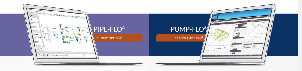
With the number of pumping stations found throughout water distribution and wastewater collection systems, there are many opportunities for improving energy efficiency. However, with the seemingly endless variety of design options, finding the optimal solution can be daunting. Fortunately, for the modern engineer, fluid piping software provides the necessary analysis to design an efficient pumping system or evaluate current installations for potential improvements.
Though fluid piping software has been in existence for more than 35 years, it has only recently received considerable attention. The software allows engineers to conduct the type of rigorous design evaluations that they have not previously been able perform. In the past, engineers often relied on standard designs for new pumping system installations. For example, typical design practice for lift stations involved specifying a duplex pumping arrangement in which each pump is sized for peak capacity. The units alternate operation to ensure even wear and the duplex configuration allows one pump to be taken offline for maintenance. This basic design has not changed much in the past 50 years, and for good reason—it works and provides redundancy to avoid major failures3. Clearly, the inherent design is sound, but software allows the user to look at ways of improving the system, which may lead to greater energy efficiency and lower maintenance and operating costs.
For example, consider a case in which an existing lift station could be evaluated to optimize the design for improved energy efficiency. The current system includes a wet well lift station with two 40 horsepower (hp) submersible pumps pumping into a 5,000 foot, 8 inch force main. There is an elevation gain of about 55 feet from the discharge of the submersibles to the inlet of the gravity sewer. Figure 1 shows a schematic of the lift station model. The daily capacity of the system is approximately 320,000 gallons and the pumps are sized for a peak design flow rate of 800 gallons per minute (gpm) at 101 feet of head. Currently, the average pump operation is about 6.7 hours per day. Assuming a power cost of $0.10 per kilowatt hour (kWh), the annual energy usage and cost to operate the lift station is 56,931 kWh, or approximately $5,693.
By modeling the lift station with all relevant design information and operating conditions, inefficiencies can be quickly identified. At the peak design, with a flow rate of 800 gpm, there is an excessive head loss of 57 feet through the force main, which can essentially be thought of as wasted energy that has been put into the pump.
From Figure 2 we can see that the head loss in the force main can be drastically reduced by lowering the flow rate, a result of the characteristic second-order relationship between head loss and flow rate in a pipe. Considering the pump only needs to be capable of delivering the peak flow rate a few times throughout the day, by operating the lift station at a reduced flow rate we can significantly lessen energy usage and operating costs. To accomplish this, some lift station designers are employing the use of a jockey pump, which is typically less than 10 hp and is included in addition to the traditional duplex pump configuration. The main duty pumps are run only a few times a day during peak hours while the jockey runs most of the day to pump the off peak inflow to the lift station3.
Using hydraulic simulation software it was determined that a flow rate of about 160 gpm for the jockey pump would be sufficient for off peak operation and would reduce the head loss in the force main from 57 feet to 3 feet, as shown in Figure 2. The jockey pump will run for about 18.3 hours per day at the design flow rate and the duty pump will run about three hours per day. A 3-hp jockey pump was selected from within the software by digitally searching a manufacturer’s catalog for pumps that satisfied the design specifications of the lift station model.
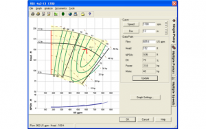
Looking at the system resistance curve plotted against the pump curve in Figure 3, we can see that the pump will be operating just to the left of its best efficiency point (BEP). Certainly, a pump with higher overall efficiency that intersected the system resistance curve closer to the pump’s BEP could have been found, but for the example, only a single manufacturer’s catalog was utilized. Regardless, the chosen pump is operating at an efficiency of 72.3 percent and the flow rate falls within 88 percent of the BEP flow, which should help to ensure prolonged life.
After assessing the performance characteristics of the jockey pump, its operation in the lift station model was evaluated. The only concern encountered with using the jockey pump was a potential accumulation of solids in the force main, due to the lower flow rate. The velocity through the force main at 160 gpm is about 1 foot per second, less than the minimum recommended 2 feet per second for solids removal. However, the operation of the duty pump during peak hours should be sufficient to prevent clogging.
An operating cost analysis performed in the software showed that the new design would consume 43,621 kWh per year with an annual cost of $4,362. This analysis indicated that the use of a jockey pump would significantly reduce the energy usage of the lift station. Table 1 shows a comparison of the two designs, which indicates an annual cost savings of $1,331 and energy savings of 13,310 kWh.
Despite the long daily runtime of the jockey pump, its low power consumption results in an overall more efficient system. The 3-hp jockey pump should not require a significant investment, and the payback period would likely justify the expense. Additionally, the reduced daily run time of the duty pumps will help increase their usable life and reduce maintenance costs. Since the duty pumps represent much greater capital and maintenance costs compared to the jockey pump, this design offers operating cost savings and should yield a significantly reduced life cycle cost for the lift station.
| Design | Annual Power Usage (kWh) | Power Savings | Annual Operating Cost | Operating Cost Savings |
| Duplex | 59,631 | – | $5,931 | – |
| Duplex w/ Jockey | 43,621 | 13,310 | $4,362 | $1,310 |
Table 1. Comparison of the power usage and operating cost for the two designs (assuming $0.10 per kWh)
The example illustrates how fluid piping software can be used to quickly evaluate the efficiency of any pumping system. In less than an hour, a model of the the lift station was created, energy usage was determined, an appropriate pump for the new design was evaluated and selected and energy usage and operating cost of both designs was compared. However, an additional benefit of the software lies in compounding the analysis and evaluating all design options and elements. If, in the example new pump station were being designed, triplex pump arrangement would have been considered, or the use of variable frequency drives to achieve operation at lower flow rates during off-peak hours.
References
- Energy Efficiency in Water and Wastewater Facilities, EPA, 2013
- https://www.epa.gov/sustainable-water-infrastructure/energy-efficiency-water-utilities
- Municipal Wastewater Pump Station Design Problems and Solutions, Jeff Chapin, 2006.
- Piping System Fundamentals: The Complete Guide to Gaining a Clear Picture of Your Piping System, Ray T. Hardee, ESI Press, 2008
https://empoweringpumps.com/products/engineered-software-pipe-flo-professional-fluid-flow-analysis-software/