1. B-90ft
2. B-90ft
3. B-90ft
4. C-95ft
5. A-87ft
Explanations:
Static Head = Elevation Head Differences + Pressure Head Differences
Elevation Head = (Elevation of product tank liquid surface) – (Elevation of supply tank liquid surface)
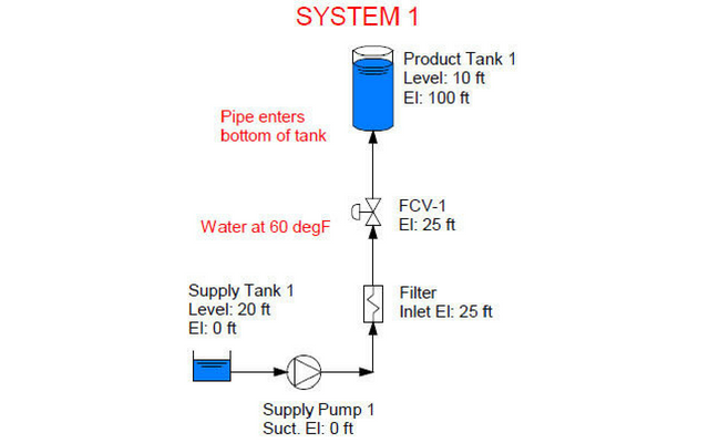
System #1:
Static Head = (100 ft + 10 ft) – (0 ft + 20 ft) = 90 ft
System #2:
Even though the pipe enters the middle of the tank at 105 ft elevation, there is still another 5 ft of liquid above the pipe penetration. The discharge of the pump “feels” a column of water that is 110 ft high, and the suction feels 20 ft of water from the supply tank. Static Head = (105 + 5) – (0 + 20) = 90 ft
System #3:
Even though the pipe rises to 120 ft elevation, it drops back down and discharges at 105 ft elevation and there is still another 5 ft of liquid above the discharge of the pipe. The energy it takes to raise the fluid from 105 ft to 120 ft going up is recovered by the siphon effect as the fluid drops from 120 ft to 105 ft to the outlet. The net effect is that the pump still has 110 ft of head it has to push against at the discharge and 20 ft of head at the suction to help it. Static Head = (105 + 5) – (0 + 20) = 90 ft.
System #4:
The outlet of the pipe is at 115 ft elevation, even though it rises to 120 ft then drops back down (5 ft of energy is recovered due to the siphon effect). Static Head = (115) – (20) = 95 ft
(NOTE: When just starting up, the pump has to overcome 100 ft of static head to reach the top of the loop)
System #5:
Since static head is in reference to the fluid going through the pump, System 5 requires a density compensation of the 85 ft of liquid from the heat exchanger to the product tank. Check out the related article from our Knowledge Base that talks about how to do it.
The density of water at 200 F is about 60.1 lb/ft^3, and at 60F it’s about 62.4 lb/ft^3.
85 ft x (60.1/62.4) = 81.9 ft.
Total static head = (static head from pump to HX + head from HX to product tank – head from supply tank to pump)
Total static head = (25 ft + 81.9 ft) � 20 ft = 86.9 ft.
The net effect of the temperature (density) compensation is to reduce the static head by 3 ft to 87 ft.