Author: Howard W Penrose, Ph.D., CMRP, President, MotorDoc® LLC
Repair and Communication
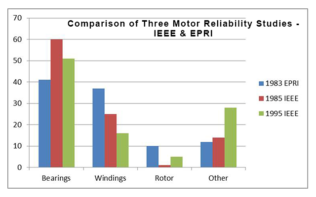
In a series of studies performed by the Institute of Electrical and Electronics Engineers, Inc. (IEEE) and the Electric Power Research Institute (EPRI) from 1983 until 1995 [1], [2], [3], covering all industries, bearing faults followed by winding faults were prevalent (Figure 1 above). It was also found in these studies, as well as one performed by Advanced Energy [4] and another performed by the Electrical Apparatus Service Association (EASA) [5], that in many cases repaired motors do not last as long as they should due to poor repair practices. It can also be argued that some part of the repetitive failures of these motors is due to a lack of diagnostics, or forensics, reported to the motor owner through the repair process.
While a number of studies and surveys performed all the way through 2013 identify that good repair will last longer, few have identified the importance of providing the motor owner with feedback on the possible root causes. How do the owner’s maintenance department or reliability engineers respond to a report of ‘replaced bearings,’ or ‘rewound stator,’ in such a way as to prevent the problem from recurring?
In a significant leap, the difference between the 2003 and 2013 Motor Diagnostics and Motor Health Studies (MDMH) [6] was that in 2003, 56% of organizations had electricians responsible for electric motors and only 2% had reliability engineers. In 2013, it was found that the number had shifted to 43% reliability engineers and 26% electricians with a significant drop in mechanical and general maintenance personnel. By definition, a reliability engineer requires feedback in order to ply his trade, meaning that an understanding of the equipment failure, including potential root causes, as well as corrective recommendations, become that much more critical in the repair process.
For instance, if the motor has failed because the bearings were noisy, what caused them to become noisy? Were they over greased? Under greased? Belt over-tension or misalignment? Is there bearing fluting due to shaft currents? This information, including recommendations, will assist the motor owner or reliability engineer in developing a plan to mitigate future problems. For example, if the bearings in the motor operated by a VFD appear as in Figure 2, an indicator of shaft currents, corrective action using a shaft brush, or shaft brush and insulated bearing, can be taken. This also means that either the repair facility’s representative should be asking application questions and/or the motor owner should be providing that application information.

Figure 2: Bearing Fluting Caused by Shaft Currents
Rewind related failure modes must also be identified. If a winding has a single phase event and the information is not identified, chances are good that the failure will happen again. Installing an electronic overload with single phase protection would mitigate similar failures in the future. If a winding fails due to overload, this knowledge is beneficial to the motor owner so that they may enhance their level of overload protection.

Figure 3: Overloaded Winding
Repair Process Impact on Reliability
As noted by the US Department of Energy: “Of the quality assurance procedures shops used, 40% were repair procedure specifications, 25% were test specifications, and 21% were EASA standards. Only one of the 65 shops surveyed used any form of quality assurance testing.” [7] In fact, per the same report, almost half of the shops surveyed performed no winding tests during the entire repair. Eighty-one per cent of repair shops also reported that they changed winding configuration in electric motors through the repair process primarily for shop preference or ease of winding (73%), 10% with the owners’ knowledge and only 4% for the purpose of reliability or durability. The remainder did not provide a reason.
Through all of the studies performed related to electric motor repair, it has been noted that proper repair practices are vital to the reliability of the repaired electric motor. While the studies primarily focus on energy consumption, or efficiency, of the machines, the 2013 MDMH identified a solid 0% of interest in energy as a driver for a motor program (only 3% in 2003). The key driver for the motors program was identified as reliability (75.5%).
Following the reliability perspective and study results, the only reason for modifications from the original manufacturer’s design must be for improvements to the durability of the machine or engineering modifications to improve the reliability of the application. Modifications to make the repair ‘cheaper’ or because the repair shop does not maintain the appropriate metric or half-size wire does not benefit the user and can become very expensive in the short run and extremely expensive in the long run. Companies that peen or glue bearing fits should be strenuously avoided. Such repairs should only ever be considered to ‘get by’ while awaiting a replacement, knowing the risk of catastrophic failure is high.
Properly maintaining fits through testing and machining to tolerance using welding, sleeving or remanufacturing will maintain potential bearing life, as well as keeping friction and windage losses down. While these losses relate to energy consumption, they also result in increased operating temperature. Just as with winding insulation life, for every 10°C increase in bearing temperature the grease life reduces by half.
In 1984, David C. Montgomery published a paper which identified the impacts of core loss increases of 50%, 100%, 150% and 200% and related it to temperature rise, resulting insulation life, and impact on grease/bearing life based upon winding removal processes using high temperatures [8]. The machine used for the example was a 50 horsepower, 3600 RPM drip-proof motor. He also related that the impact is greater as the motor size increases.
Table 1: Impact of Core Losses Due to Burnout Ovens
| % Core Loss Increase | Watts/lb. Increase | Temperature Rise Increase | % Potential Insulation Life | Approximate % Grease Life |
| 50 | 515 | 7°C | 62 | 85 |
| 100 | 1030 | 14°C | 38 | 69 |
| 150 | 1545 | 21°C | 24 | 58 |
| 200 | 2060 | 29°C | 14 | 46 |
The issue related to burnout oven stripping of electric motors has been a long-standing one. The use of high temperature stripping results in a limit to the number of times a winding can be rewound, an impact on the mechanical fits and soft foot, increase in associated greenhouse gas emissions due to drops in efficiency, and community health issues [9]. The use of repair processes that involve high temperature stripping must be carefully considered due to the potential impact on overall system reliability. While close monitoring of thermal stripping methods is strongly recommended by studies, professional societies and trade associations, the number of cores damaged due to excessive temperatures is on the rise. This can be noted if the user has a motor that has an increase in operating current. Just the change of an amp of current relates to a significant increase in core losses and excessive shims required for alignment related to frame distortion. Mechanical and induction processes using low temperatures are available that have no negative impact on core losses [10].
Testing through the entire repair process is critical and must be recorded, as well as performed with calibrated equipment. Testing must include phase resistance, insulation resistance, high potential testing, surge testing, rotor testing, core loss testing and other tests depending upon the type of electric motor. Mechanical tests must be performed with calibrated measuring instruments. Running tests should include voltage, current, vibration, and audible tests. With the low cost of digital memory, digital photos should be taken of the motor when it is received by the repair shop and prior to shipping, at a minimum, with unusual faults photographed and provided in a final report, along with any data required by the reliability engineers. It is also recommended that forensic analysis and root cause failure analysis is performed with input by both the user and repair facility when critical machines fail or there are repetitive failures.
Installation Considerations
The author has had end users inquire, “Why should I have a Cadillac repair when I have Yugo mechanics?” Meaning, what is the point of having a reliable repair when the machine is going to be misaligned, mis-tensioned, or other issues. There is a simple answer that is not even buried in reliability or industrial engineering: two unreliable systems create an even more unreliable system. A combination of poor installation with reliable repairs has the potential to increase the reliability of the system over a system in which both installation and repair are less than optimal. In effect, a highly robust repair will result in a system that can better withstand poorly applied or installed motors.
For instance, a cheap repair has a poor bearing installation and a damaged core. Instead of a motor that would last 10 years (120 months), we end up with a motor that lasts about 6 months. When applied to the reliability formula (Equation 1), the result is a reliability of 0.905 (90.5% chance of surviving the first year) for the reliable repair example and 0.05 (5%) for the less reliable motor.
Equation 1: Reliability Formula
Where λ is 1/Mean Time Between Failure (MTBF) and t is time in months
If we now apply a maintenance technician who has a success rate of improper installation resulting in an average life expectancy of a motor installation being about a year due to such things as loose connections, improper belt tension, alignment, etc., his reliability would be 0.368 (36.8%).
When this technician is paired with the low reliability repair, the result is (0.05*0.368 = R) 0.0184, or a 2% chance the motor will survive the first year. If, however, we use the high reliability repair, then the result would be (0.905*0.368 = R) 0.333, or a 33.3% chance the motor will survive the first year.
While it is important that an organization improve the quality of installation and maintenance, it is significantly obvious that a higher quality repair is even more critical in an evolving maintenance department. Considering that the average cost per hour downtime, per both the 2003 and 2013 MDMH studies, is $10,000/hour for critical machines, the improvement in repair savings can be staggering.
Bibliography
- Albrecht, Appiarius, McCoy, Owen and Sharma, “Assessment of the Reliability of Motors in Utility Applications – Updated,” IEEE Transactions on Energy Conversion, Vol. EC-1, No. 1, March, 1986.
- Motor Reliability Working Group, “Report of Large Motor Reliability Survey of Industrial and Commercial Installations, Part 1,” IEEE Transactions on Industry Applications, Vol. 1A-21, No. 4, July/August, 1985.
- Thorson and Dalva, “A Survey of Faults on Induction Motors in Offshore Oil Industry, Petrochemical Industry, Gas Terminals, and Oil Refineries,” IEEE Transactions on Industry Applications, Vol. 31, No. 5, September/October, 1995.
- Advanced Energy, Achieving More with Less: Efficiency and Economics of Motor Decision Tools, Advanced Energy, USA, 2006.
- EASA/AEMT, The Effect of Repair/Rewinding on Motor Efficiency, Electrical Apparatus Service Association, Inc. and Association of Electrical and Mechanical Trades, Inc., USA and UK, 2003.
- Penrose, Howard W., 2013Motor Diagnostics and Motor Health Study, motordiagnostics.com, April, 2013.
- Schueler, Leistner and Douglass, Industrial Motor Repair in the United States, Bonneville Power Administration, USA, 1995.
- Montgomery, David, “The Motor Rewind Issue – A New Look,” IEEE Transactions on Industry Applications, Vol 1A-20, No. 5, September/October 1984.
- Penrose, Howard W. and Dreisilker, Leo F., “The Mechanical Effects from Thermal Stripping Induction Motor Stators,” 1997 EIC/EMCWA Conference Proceedings, IEEE, 1997.
- Penrose, Howard W. and Dreisilker, Leo F., “Evaluation of Induction Warming Stator Cores for Coil Removal,” Conference Record of the 2012 International Symposium on Electrical Insulation, IEEE, 2012.
About the Author
Howard W Penrose, Ph.D., CMRP is president of MotorDoc® LLC, Web Editor-in-Chief of the IEEE Dielectrics and Electrical Insulation Society, and the Vice Chair of the Society for Maintenance and Reliability Professionals, Inc. He can be contacted at 800-919-0156 ext 0 in the USA or 630-310-4568 outside of the USA or hpenrose@motordoc.com.


