Contributor: EagleBurgmann
Centrifugal compressors are used in processes for producing oil, petroleum, petrochemical and chemicals. They are also used for natural gas processing, such as liquefying natural gas and transportation pipelines. Due to the cost of a compressor package, backup compressors are usually not part of purchased equipment, even though they are critical for continued production in many processes; therefore, they require high availability, reliability and safety to meet industry requirements.
Centrifugal compressors are equipped with seals to ensure the process gas stays within the compressor, typically dry gas seals. The seal leakage is monitored and often shuts down and vents the compressor when high leakage occurs, as this high leakage indicates a seal failure. Shutting down a compressor on high seal leakage manages the safety requirements and avoids possible damage to the equipment.
To ensure the reliability of dry gas seals and prevent situations that lead to high seal leakage the most important factor is supplying quality gas to the seals any time gas pressure is injected into the compressor or gas pressure is present in the compressor. There have been many studies on the causes of dry gas seal failures and they all identify contamination as the leading cause due to insufficient or poor quality supply gas.
Contamination of Dry Gas Seals through process gas
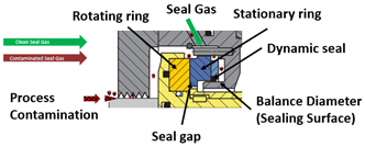
There are two key elements within a Dry Gas Seal that are affected the most by contamination. One is the 3 to 5 µ gap between the stationary and rotating seal rings. The rotating seal ring has integrated grooves to generate a gap between the seal rings and to provide a stiff gas film between them during operation. The second is the dynamic seal used on the stationary ring to compensate for compressor rotor axial movement in relation to the compressor case. This axial movement is caused by varying loads on the compressor rotor and vibration. There is also changes in axial position with case expansion from heat and pressure. It is critical to manage all of these factors effectively with the dynamic seal. This can only be accomplished when the stationary seal ring moves unhindered to maintain the gap between the seal rings.
For reliable trouble free operation of dry gas seals, the seal gap and dynamic seal, must not be contaminated. This is the purpose of the seal gas, to provide quality gas to the seal; no particles that will expand the seal gap or clog the gas grooves. It also ensures not contamination that would affect the operation of the dynamic seal. To ensure quality gas is delivered to the seal, a source gas is taken from the discharge of the compressor, passed through filters or a gas conditioning system, through a flow control system and into the seal cavity. The seal gas creates the ideal environment for the seal to operate and provide the means to deliver the reliability expected from a dry gas seal.
Seal gas flow is simple to achieve during operation, due to the higher discharge pressure compared to the suction pressure typically present in the seal cavity. The challenge occurs during other compressor operating conditions where there is little or no differential pressure between discharge pressure and seal cavity pressure, so sufficient seal gas flow can’t be produced. Such instances are during compressor pressurization, startup, pressurized hold and other transient conditions. At these times dirty process gas is allowed into the seal cavity, which affects the seal gap and dynamic seal.
As the product in a compressor is typically considered clean gas, many people don’t understand how it affects the dry gas seal reliability. They know the gas leaking through the seal gap is minimal and believe this is clean gas and no detrimental effect to the seal should occur. The problem is the cleanliness of the process gas is much different than that required by the seal and the fact when gas temperature or pressure changes, components in a gas can turn to liquids. So when the seal is exposed to untreated process gas it does affects the seal operation and reliability. The seal cavity and seal become contaminated with gas that has particles larger than 3 micron and gas components that are liquid or turn to liquid, as it passes through the seal gap; this leads to seal failures.
Contamination for a dry gas seal is split into 2 categories, one is particle contamination and the second is liquid contamination. The following sections discuss the effects of contaminating a seal with each.
Contamination by particles
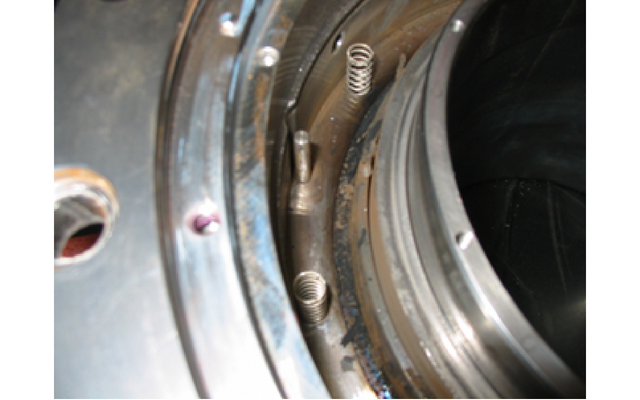
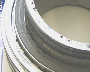
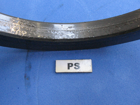
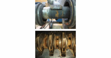
When small enough particles enter the seal, less than 3 micron, they blow through the seal. Larger particles become trapped inside the grooves or seal gap. If the particle are trapped in the grooves and build up, the seal loses its effectiveness to maintain the seal gap. When larger particles are forced through the seal rings, they will open the seal gap or damage the seal rings as they pass through. All of these contamination scenarios lead to high seal leakage.
In addition to the sealing gap, particles also affect the dynamic sealing element. The dynamic sealing element is an O-ring or elastomer free sealing device between the stationary seal ring and a stationary sealing surface (balance diameter). As mentioned previously this assembly must move freely to maintain the seal gap when the position of the compressor rotor changes in relation to the compressor case. If the dynamic sealing element has any accumulation of debris around it, the stationary ring axial movement is hindered. A sticky dynamic seal will open a flow path around the seal ring, which increases seal leakage. The stick dynamic seal can also eliminates the seal gap, causing the rotating and stationary rings to contact; producing erratic leakage. Eventually sufficient damage is caused and the seal fails.
Adequate seal gas filtration, conditioning and seal gas flow are the key factors to prevent this type of contamination from entering the seal. So when ever pressure is present in the compressor it is critical to maintain quality seal gas flowing into the seal cavity
Contamination by liquids
As mentioned earlier, if the temperature or pressure of a gas changes, components in the gas will turn to liquid. When a compressor is hot during normal operation, the operating temperature ensures the seal gas remains in a gaseous state for most applications. So all components remain in a gaseous state as it flows from the discharge tap, through the seal gas system, into the seal cavity and through the seal – dropping in pressure and temperature from discharge pressure and temperature down to atmospheric pressure and temperature. The gas temperatures can also reduce even more due to the impact of the Jewels Thompsons effect, as the gas flows through the entire system dropping in pressure.
The bigger concern is when the compressor is not running, as the gas in the seal cavity can cool to the ambient temperature. At this lower temperature and suction pressure, the gas conditions will cause some gas components turn to liquids or form liquids as the gas pressure drops across the seal gap to atmospheric pressure. To determine when components in a gas turn to liquid, a dew point analysis must be completed on an accurate gas composition.
When liquids enter the seal gap or form in it, high shear forces are created, which generate heat. The heat produced leads to gap instability, causing contact between the rotating and stationary seal rings, damaging them and leading to a seal failure. If a failure does not occur during operation with the liquid contamination, the seal will fail at the next subsequent start due to increased shear forces on the seal rings or shortly after due to heat generated between them. Liquid contamination occurs, when gas dew point is not considered, a dew point analysis is not completed, an inaccurate gas composition is used to complete the dew point analysis, or unconditioned seal gas is allowed in the seal cavity during transient conditions.
Effectively conditioning seal gas to ensure no liquids form in the seal cavity or seal gap and preventing process gas that has the possibility of forming liquids into the seal cavity are the two key factors to prevent seal failures related to liquids. For both particles and liquids it is of the utmost importance to maintain seal gas flow into the seal cavity, so the ideal seal environment is produced. This ensures particle or liquid contamination won’t enter the seal cavity or seal, which will reduce its reliability.
Contamination during pressurized stand still conditions
Loss of seal gas flow is common, which is supported by the seal failure studies. One practice associated with loss of seal gas flow is pressurized standstill. When a compressor is stopped it is held with pressure in it for a specified length of time. This allows the
compressors to be placed back into operation quickly if needed again. If no means is provided to maintain seal gas flow during this time, process gas leaks into the seal cavity, which contaminates the seal. To minimize the amount of process gas entering the cavity, the compressor is vented after a short period of time. As stricter environmental regulations make it more challenging to vent a compressor without penalties this procedure has become more difficult to do. There are also instances where a compressor must stay pressurized for extended periods of time to ensure a quick restart responding to varying demand. If the seal is not effectively protected, seal failure commonly occurs, gravely affecting the dependability of the equipment for meeting production requirements, profitability and environmental regulations. As identified above, particles in seal gas or seal cavity, or liquids that form in a seal gas, are the root causes for the majority of seal failures. To prevent these failures from occurring it is essential a clean and quality seal gas is provided to the seal. This maintains a reliable seal that will not fail because of standstill conditions and prevents failures when restarting or shortly after restarting a compressor.
To prevent dirty or wet process gas from entering the seal cavity, seal gas flow must be maintained. One of the common ways to achieve this is with a seal gas booster. Typical seal gas boosters used over the years have been air driven, but the challenge with them is they are not the right equipment for the application. As a minimum flow is required to ensure a clean seal cavity, a piston type booster must work hard to deliver the required flow, which leads to poor reliability and extreme maintenance requirements. Most times they don’t achieve a satisfactory safety margin above the minimal flow and sometimes are challenged to even provide sufficient flow. To deliver sufficient flow multiple units are typically required. Another downside to piston boosters is the amount of instrument air consumed when using them. If multiple units are incorporated to meet sufficient seal gas flow the air demand becomes even more challenging.
To provide an idea of the air requirement and how many units are should be provided to effectively support the application, below is an example for a pipeline application:
Shaft size: 150 mm (5.9")
Pressure: 70 barg (1,015 PSIG)
Temperature: 23 °C (73.4 °F) Required flow for 5 m/s (16.4 ft/s) at twice the labyrinth clearance: 389 Nm3/h (229 SCFM)/seal – 778 Nm3/h (458 SCFM) for 2 seals on a beam compressor.
Output of piston booster at 90 cycles/min.: 332 Nm3/h (196 SCFM)
Drive air required for one unit: 62.6 Nm3/h (36.8 SCFM)
Based on the size and operating condition for the above example, seal gas flow for each seal is more than the output flow produced by one piston booster. To meet the recommended flow for two seals, three boosters should be used. This would then provide sufficient safety margin to ensure even unforeseen circumstances are managed effectively. The air utility needed for these 3 boosters to deliver the recommended flow is 132.5 Nm/h (78 SCFM; a substantial air requirement to effectively support seal gas flow.
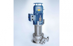
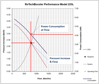
EagleBurgmann developed the RoTechBooster, so sufficient seal gas flow, reliability and simplicity were provided to customer which they have been looking for since the inception of seal gas boosters. As it is electric driven, minimal capital and space are required, compared to a piston booster and its associated equipment for utilities to support its operation. Below is the performance of a RoTechBooster and utilities for supporting the same application:
Output of an centrifugal booster: 778 Nm3/hr (458 SCFM)
Power consumption: 4.1 kW
Conclusion
The industry has confirmed contamination is the leading cause for dry gas seal failures. As identified in this article, if process gas or inadequately conditioned seal gas is provided to a dry gas seal, it will affect the seal reliability, which leads to failures. The best means to prevent this from occurring is a reliable seal gas booster. The common piston type boosters are challenging for users, because of the costly supporting equipment, high maintenance and poor reliability.
When users are looking for reliability to meet their needs they look to centrifugal equipment, the RoTechBooster is rotating design proven to delivery the reliability users expect. With a RoTechBooster they can now maintain a compressor in pressurized hold until absolutely necessary to vent it or even restart it and never have a concern with a seal failure occurring. The RoTechBooster booster is a reliable, cost effective means to support your dry gas seals and improve compressor reliability, increasing profits and preventing emissions. Rely on excellence, rely on the EagleBurgmann RoTechBooster.
For more details and to order of RoTecBooster, please contact your personal dedicated technical expert, Emery Johnson via email at Emery.Johnson@eagleburgmann.com.

