Darlington nuclear power plant has 16 identical feedwater pumps across its four operating units that for many years experienced high pump-drive end vibrations above alarm level. At Darlington, as at many other nuclear plants, there is an ongoing effort to improve running conditions on rotating equipment while reducing periodic maintenance. By closely studying the pump-drive end vibration problem and methodically researching possible solutions, Darlington personnel were able to both improve performance and reduce periodic maintenance with one solution: the replacement of the original gear coupling with a flexible coupling.
About the pumps
Each unit at Darlington has four 33 percent–duty Sulzer Bingham Model 300300450 MSD main boiler feed pumps. Each is a horizontal, two-stage, motor-driven unit with a casing that is a horizontally split volute. The first-stage impeller is double suction, and the second stage is single suction.
The pumps have journal-type radial bearings with babbitt-lined shells, and the thrust bearing, located at the nondrive end of the pump, is a Kingsbury tilting pad type. The pump and motor bearings are lubricated with cooled and filtered oil supplied by a shaft driven pump, and a motor-driven auxiliary oil pump supplies oil when the pump is started up. Shaft sealing is done by cold water gland injection to a packingless stuffing box. The pumps had a standard gear coupling, per the original design of the pump set (the coupled motor and pump). The design condition—the normal operating point for the pump, also referred to as the duty point—is 485 liters per second at 630 meters total dynamic head with 150 °C water.
The pump motor is a 3600-kW, 3600-rpm Canadian General Electric unit, with babbitt radial bearings supplied with oil from the pump-driven oil pump. The windings are cooled by a shaft-mounted fan blowing through a water-supplied heat exchanger.
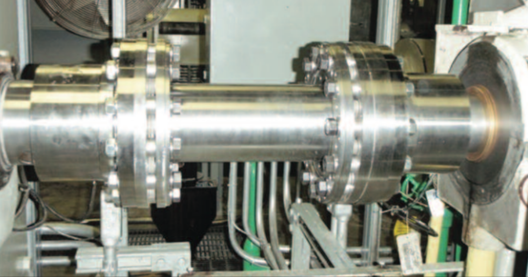
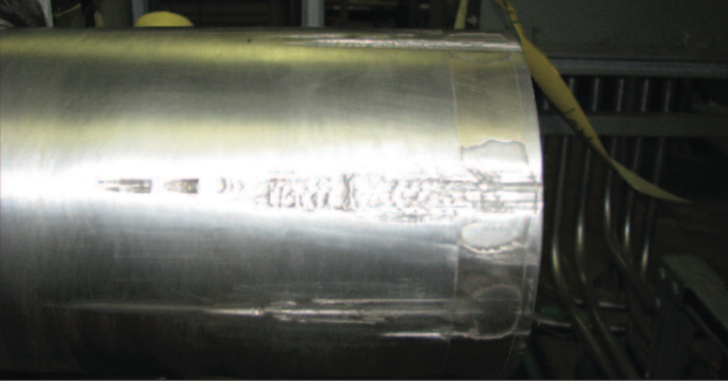
Before and after: Several deep gouges resulted from the removal of the motor shaft on one of the feedwater pumps at Darlington (top of article). Instead of having to remachine the shaft, workers were able to clamp the new hub over the problem areas (above). (Photos: OP)
The problem area
For many years, pump/motor relative shaft offset due to hot versus cold alignment (thermal growth) of the pump sets caused fairly heavy dynamic loading–induced vibrations on the pump-drive end bearing with the vibrations consistently exceeding the alarm limits. To eliminate the nuisance alarms, the alarm limits were increased from 60 micrometers (2.4 mils) to 85 mm (3.4 mils). Even so, plant personnel wanted to reduce the vibrations to avoid the risk of pump unavailability, which, in the event that two of the four pumps were unavailable, could lead to a unit derating.
Finding the solution
Plant personnel suspected that pump set shaft offset due to thermal growth was causing the pump gear couplings to “lock,” which in turn caused the pump vibrations to increase from elevated levels to above alarm levels. Consequently, Darlington’s Component Engineering working group decided to replace the pump gear coupling with a flexible coupling. Another benefit of replacing the gear couplings with flexible couplings was the reduction in regular maintenance, such as greasing and checking for wear.
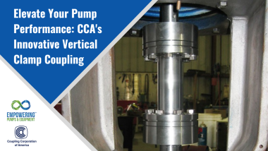
With the help of the pump vendor, Sulzer, several options were explored, and a decision was made to go with a coupling with very low axial and angular spring rates, made by Coupling Corporation of America (CCA). It was determined that the lower spring rates would help reduce the dynamic effect of any misalignment, as well as reduce vibration transmissibility through the coupling. The flexible element of the coupling is neither a disc- nor a diaphragm-style, but is something of a hybrid of the two.
Before the final coupling selection was completed, Sulzer put the new design through a rotor analysis to confirm that it would be compatible with the existing equipment at the Darlington station.
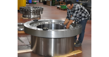
The chosen coupling also provided the benefit of the addition of keyless Anderson Clamp Hubs on the pump and motor shaft. These new hubs create interference mechanically using loading screws and taper fits at the hub and the collar for each hub, allowing for the elimination of any heat or hydraulics typically needed for coupling hub installation and removal. In addition to time and manpower savings, the new hub design also provided personnel with the capability to adjust the axial position of the hub on the motor shaft to account for changes in axial spacing due to thermal growth and to magnetic center and motor mounting issues.
The new Anderson Clamp Hubs provided an immediate benefit during their first installation. The removal of the original gear hub resulted in several deep gouges on the motor shaft (see accompanying photo). Typically, this type of problem would have called for the shaft to be remachined, along with the hub, but after consulting with CCA, workers were able to clamp the new hub over the problem areas without any issues.
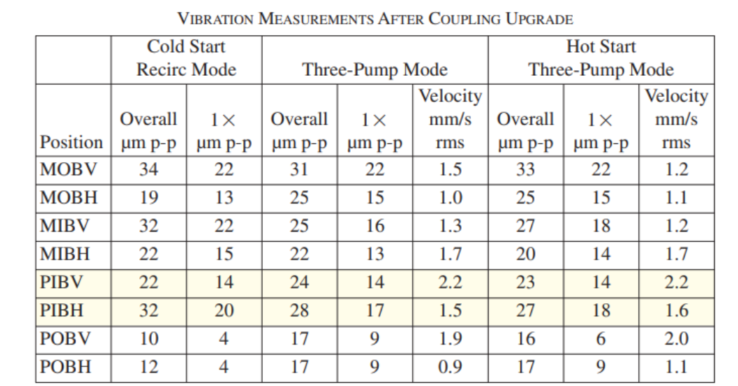
Yellow highlighting indicates numbers that are a direct comparison to the original pump vibration levels of 85 µm
(3.4 mils) p-p
M = motor P = pump O = outboard I = inboard B = bearing V = vertical H = horizontal p-p = peak to peak
rms = root mean squared
The results
The new coupling was installed on one pump (3-43210-P2) in September 2009, and the improvement was immediately noticeable. With the original coupling, the pump-drive end vibrations were, as noted earlier, roughly 85 mm (3.4 mils). With the new coupling, they dropped to 15–20 mm (0.7 mils). Similar improved vibration measurements were also taken at the other bearings in the system. Running in both four pump initial start and three-pump hot condition, the vibration levels remained very similar (see table).
After a trial period during which essentially no problems were encountered, the new coupling was installed on a second pump (3-43210-P1) in February 2010, with the same positive results. With the help of Sulzer and CCA, the pump component engineer wrote a new installation procedure to allow for successful secondary installations. The new couplings are being installed on the remaining pumps at Darlington, and the results have been consistently good for all installations.
Originally published with in Nuclear News
Mark Robinson <mark.robinson@opg.com> is Senior Pump Component Engineer at Ontario Power Generation’s Darlington nuclear generating station, and James H. Anderson III <JHA3@couplingcorp.com> is Vice President of Coupling Corporation of America.

