Understand the Application
Shutdowns for valve maintenance or replacement are costly to plant capacity, and ultimately revenue. As end users strive to maximize their operating performance and efficiency, valve manufacturers are forced to evolve their valve designs to meet their customer’s expectations and demands. Implementing new designs and materials into the valve design is one way to keep up with the evolving requirements put forth. Another approach is to concentrate on using the best valve for the application, rather than simply looking at the design and material specifications. It is crucial that we turn our attention to the application and the process conditions present to determine what product is selected. In this article, we will look at an application solution along with valve design to address challenges faced in process industries.
LNG plants typically consist of liquefaction and gas treating areas to condition the gas to be converted into liquid form for mass transportation across great distances. The process and applications within these facilities are demanding for valves; proper review of the conditions occurring when the valve is operating should be completed before a selection is made. The following application is an example of looking at many aspects of the process and awareness of the conditions presented by the system.
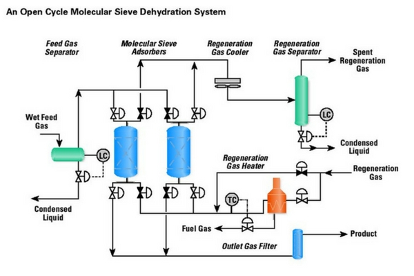
In the gas treating area of natural gas, removing moisture from the gas is an important step to protect equipment and components of the piping system. With H2S and CO2 present in natural gas feeds to the LNG facility, there is a potential to generate Sulfuric Acid and Carbonic Acid that increases corrosion rates of several materials typically used in piping systems. Dehydration, also known or referenced as molecular sieves, of the natural gas becomes an important step in protecting piping systems and plant safety (See Figure 1). This process typically will have at least two towers, though there can be multiple towers with absorption media to collect the H2O. These towers typically consist of beds holding desiccant beads. As the absorption media becomes saturated, it must be regenerated by reverse flowing with high temperature media to drive off and collect the process water for disposal. In two tower systems, one unit will be in absorption phase and the second will be in regeneration or stand-by phase. As a result, switching valves are required to isolate between the towers for efficient operation of each unit. These valves need to handle high cycles, high temperature, high pressure and varying process media with abrasives and corrosives. The abrasives and corrosives present wear potential to valve sealing and operating components, which impacts long term performance and safety.
Review the Valve and the Process
We began working with a large producer and operator of a molecular sieve system where switching valves were causing process inefficiencies. The challenges being faced were isolation and cycling failures occurring at random intervals, which required repair or replacement on average of every 18 months. Through review of the valves and process, it was found the seats and ball were being damaged by abrasives from the natural gas and desiccant beads in the towers. In review with operations team members, we learned of valves seizing or sticking during operation, caused by design and material build-up in key areas in the valve, which would require immediate attention at all times of the day.
The process conditions present were as follows:
- 1100 psig (76 barg) plant operating pressure
- 40o C to 285o C plant operating temperature
- Sour natural gas consisting of:
- 20% H2S average, ranging from 17% to 35%
- 10-12% CO2
- 8-10% H2O
- 55,000 to 65,000 ppm chlorides
- Asphaltines, sand, sulphides, mercaptans, light hydrocarbons
- Desiccant dust
As a result of the review, we realized the sealing and operating components of the valve would have to provide high wear resistance to the dynamic conditions of temperature, pressure and both abrasive and corrosive media.
The solution provided is ValvTechnologies’ V Series quarter-turn metal seated ball valve, as seen in Figure 2. The product provides a unique design in ball valves that handles the challenges and dynamic conditions of this particular application.

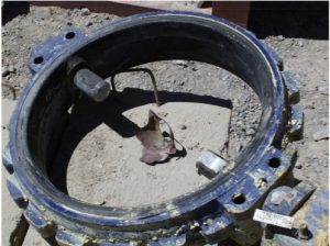
Figure 2: ValvTechnologies 3” Class 900 V Series valve for molecular sieve regeneration switching installed in July 2003.
Between the ball and seatBall valves are generally categorized as either fixed or floating based on the position or movement of the ball. Trunnion mounted ball valves would be a fixed ball valve design where the seats are pushed towards the ball via springs and process pressure from behind seat rings; the ball is held in position via a lower and upper stem connected to the ball. Pressure assisted or floating ball valve designs use process pressure to move the ball into and hold it against the downstream seat. In these designs, there are two potential leak paths:
- Between the ball and seat
- Behind the loose seats mounted in the body
In this particular application, rising stem ball valves were in service and the producer found repairs and replacement to be a significant expense on an average of every 18 months. The customer was looking for an alternative to reduce their costs and increase operating performance.
In a rising stem ball valve, the operation to open or close the valve is via a linear stem that is rotated by grooves and pins as the stem moves up and down. The ball is tipped away and rotated through a helix connection between the ball and stem. A lower stem at the base of the ball holds it in position while the valve is cycled open or closed.
The ValvTechnologies’ V Series valve can be categorized as a floating fixed ball design with an integral seat machined into the body, which eliminates one of two potential leak paths previously mentioned. The floating fixed ball design is used as the ball is not connected to the stem or body, but is held in position by an upstream seat and a heavy duty Belleville Spring (Figure 3) to address the second potential leak path between the ball and seat. As a result, it does not rely on pressure to push the ball onto the seat to provide isolation, even in low pressure conditions that are challenging for conventional floating ball valves.

Figure 3: ValvTechnologies’ V Series cross section view with arrow pointing to the Belleville Spring
In this application, wear resistance is a factor for long term service life; ValvTechnologies’ RiTech® coating (Figure 4) provides the required wear resistance to the abrasive debris present in the natural gas stream. RiTech® is a HVOF (high velocity oxygen fuel) coating process, where chrome carbide is melted and applied to the ball and seat of the valve. The resulting hardness is between 66-69 Rc (Rockwell C), which compares to stainless steel at 18 Rc, Stellite at 42 Rc and diamond at 92 Rc. It is a very hard coating that protects the surfaces from wear against abrasives. The ball and seat are mate lapped to provide an exact surface match between the seat and ball for zero-leakage isolation performance. As part of ValvTechnologies’ Quality Control Procedures, all valves are tested according to the requirements of ASME B16.34 and FCI 70-2 to measure shell and seat isolation performance. To meet the seat isolation test standard, valves are pressurized to 110% of the pressure rating; which for Class 900 valves would be 2,442 psig (168 barg). ValvTechnologies conducts a low-pressure seat test at 1,000 psig (69 barg) in Class 900 valves to verify zero-leakage performance using nitrogen gas, which is a more difficult medium to isolate compared to air. This low pressure test reduces the seating load forces and as a result, makes it more difficult to provide zero-leakage performance in comparison to the requirements of FCI 70-2.
The dynamic phases of the process subject the valve to significant temperature cycles, where the valves are exposed to normal temperature of 40o C during the absorption phase and increase to 350o C during the regeneration phase. Valve design and systems using a variety of metal materials will need to adapt well to these changing conditions. The heavy duty Belleville Spring holding the ball against the seat along with live-loaded stem packing in the ValvTechnologies’ product allow the components of the valve to expand and contract through thermal cycles. This ensures the sealing materials and components remain loaded and that the valve allows no internal or external leakage.
The differential pressure across the valve in the closed position can be a challenge for valve designs requiring pressure to increase sealing forces. When the valve is closed, many of these dehydration systems have a 7 to 14 psig (0.5 to 1 barg) pressure differential, which minimizes the loading forces created by pressure. A valve design that does not rely on pressure for seating forces is an ideal choice for this application.
Make the Right Choice
The first ValvTechnologies’ V Series valve was installed in July 2003 for regeneration switching isolation and was in service until August 2011, which increased the operating life from 18 to 97 months. Initially, the ValvTechnologies’ valves acquisition price was two times more than rising stem ball valve in service, however after just over eight years in service the cost-of-ownership was significantly lower and the down time for the plant was considerably less. The original rising stem ball valve purchase price of $9,000 and on average was $5,000 to repair every 18 months; the cost of ownership for these valves over the eight year period would have been $34,000 compared to ValvTechnologies’ valve purchase price of $19,000. In addition to this, once all switching valves were changed out to ValvTechnologies, downtime caused by valve failures or leakage was significantly reduced. The production foreman estimated the ValvTechnologies’ valves realized a $3 million benefit to the facility through zero-leakage, increased uptime and reduced maintenance.
The design elements and systems of the ValvTechnologies’ valve have addressed the challenges presented in this LNG application. The superior design of the valve allowed it to last longer than its predecessor, which increased the operating duration of the process. This was critical to increasing plant efficiency and therefore profitability for the producer. When faced with challenging severe service applications, identifying media, process and operating conditions of the application provides details that are key in selecting and configuring the right valve; doing so provides long term reliability and increased operating performance.
 Download the Infographic: 6 Key Factors to Consider When Selecting a Severe Service Valve


