Author: Frank Taaning-Grundholm, Global Sales Director, Danfoss
There are many stories about bearing current damage by variable frequency drives (VFD) due to bearing currents. Some of these stories are in fact true, but many are fairy tales come to life because no one cared to investigate the actual cause of the damage to the bearing.
Another interesting fact is that bearing current damage predate VFD’s and are regularly seen on line operated pumps as well. In these instances, it is mostly due to differences in the phase to phase voltages driving a circulating current through the motor bearings.
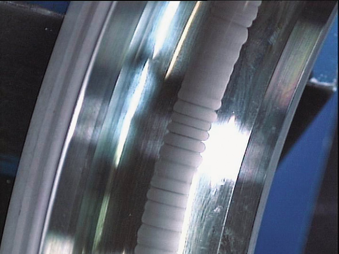
Figure 1. shows “fluted” damage to the bearing
When we are looking at drives up to 90kW/100HP, then it is rare that bearing currents are the root cause of bearing damages. In many cases, the bearings have been analyzed by the bearing manufacturer after a customer claims damage from misalignment issues. When you see fluted damage to the bearing (see Figure 1), current is most likely causing these; but if the bearing is misaligned, the track will not be as “clean” (also shown in Figure 1).
If the track is displaced from the center, and especially if the pattern appears a bit angled, then it is more likely that the actual root cause of the problem is misalignment of wrong loading of the bearing, since this causes the bearing to push through the isolating lubrication film.
With that, it is also important to note that if a bearing is not self-lubricated, then insufficient lubrication will also reduce the thickness of the film and thereby make the bearing more prone to current damage. This is one of the reasons why damages are more common on larger motors, since they are more commonly lubricated on site.
That being said, bearing currents are not a phantom phenomenon; they are real. Use of VFD’s do increase the risk of damages to the bearings. For this reason, several motor manufacturers recommend the use of isolated bearings, which should break the current flow through the bearing. There are, however, several documented cases of bearing damages even on isolated bearings, so it is not a fool-proof solution. As with many other problems, it is always better to attack the root cause than to try adding a band-aid, which in this case, isolated bearings really are not the most optimal solution.
Shaft grounding rings are also sold to manage the circulating currents in the motor and ensure that the current bypasses the bearing and goes straight to ground, thus preventing damage to the bearing. They are mounted around the shaft and bolted to the stator housing (see Figure 2).
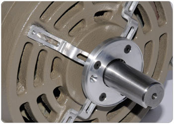
Figure 2. Shaft Grounding Rings
While this is a widely specified solution, it is again little more than a band-aid; though this is a better one than isolated bearings. It adds cost to the installation without dealing with the common mode voltages that are the actual root cause.
The best solution is to eliminate the source entirely, but due to the inherent nature of a VFD, it will create a higher potential for bearing currents. However, variable speed operation of pumps and fans provide the highest energy savings potential, and the elimination of drives is for this reason alone a very poor choice of solution, as there is no other way of regaining the energy savings achieved with variable speed.
Accepting that VFD’s are as necessary as mains fuses in modern installations, we need to focus on the effect of VFDs damaging the bearing. The root cause of the bearing currents is really the common mode currents flowing from the VFD to the motor; so eliminating those and securing equalization of the electrical potential in the installation will help to significantly reduce the risk of bearing current damages.
Filters have been introduced to the market to help prevent these circulating currents and protect the bearings. By choosing the right filter, it is possible to reduce the levels so much that there is only an extremely limited risk of bearing current damage. When these filters are applied, the cost of isolated bearings and isolation rings can be eliminated. The cost of the filters is not a pure add on cost, but a replacement for less efficient solutions.
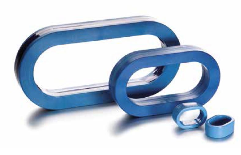
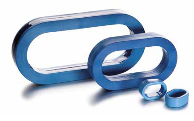
Figure 3. Common Mode Filters
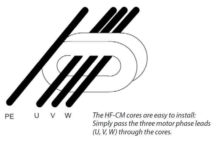
Figure 4. HF-CM cores
The design of these filters looks much like a simple ring core (see Figure 3). You simply pull the motor phases, not ground, through the core (see Figure 4) and make the installation as you would normally do. This also makes them excellent for retrofitting purposes. If you have had issues with bearing damages and suspect that it is bearing currents, then installing one of these filters might be a fast and easy solution. However, you should carefully evaluate if there are any alignment issues between the motor and the pump, as finding the root cause is always better than taking a medicine and hoping it’s for the right disease!
The bearing manufacturer can, in most cases, assist with the analysis and provide detailed information on the root cause of the damage. If in fact the cause is electrical and there is a drive installed, then my recommendation would be to involve the VFD manufacturer to investigate if there are issues with the installation contributing to the issue, before applying filters. This will make sure that other issues, which the filters do not protect from, are resolved first.