Most large-scale fluid processes are designed to run at steady state and usually include continuous segments. Operation is efficient, cheap, and safe when flows are constant and predictable. But sometimes flow changes, either intentionally or not, and controlling the wide range of consequences is neither easy to comprehend nor predict. The effects from changing flow are collectively classified as “waterhammer.” You may have heard this term in the context of your home plumbing system when you hear your otherwise-silent pipes make noise. However, this is only a small-scale example of the very serious topic.
Waterhammer is the phenomenon of pressure wave propagation that follows a change in flow – usually in the context of a sudden change. It is most common to associate this with a valve closure of some sort. Liquid systems running at steady state have large amounts of momentum. If all that momentum is stopped, the forward kinetic energy converts suddenly to potential energy in the form of pressure.
As flow comes to a stop throughout the rest of the pipes, that pressure wave propagates, just like a sound wave in air. This causes damage to pumps, pipe components, and the pipe itself. There is a logical line of consequence to follow: moving flow stops, rising pressure results, propagating waves march forth. As a result, standards and codes have existed for some time to guide engineers toward a safer design. Controlling this pressure rise is a salient concern.
High-Pressure Considerations
ASME B31.4 states that protective equipment must be in place to ensure any pressure surge does not exceed 10% above the internal design (steady state) pressure. That provides a baseline for system design. The engineer’s job is to analyze those places that can potentially change flow, such as pumps and valves, and make sure mitigation equipment is sized properly, according to the possible changing-flow scenarios.
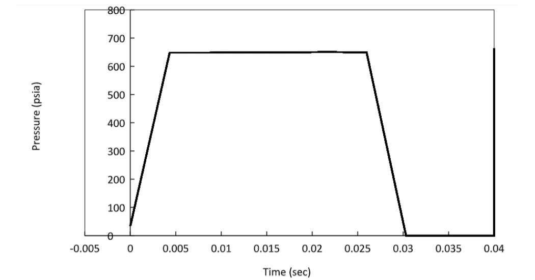
Most engineers will run calculations on the worst-case scenario, often assuming a valve closure is instantaneous. These calculations will yield an expectedly conservative pressure rise, and engineers can then design the protective equipment, such as bladders or relief valves, to control the surge and meet code. The standard formula for maximum pressure surge is the Joukowsky equation below: is the instantaneous change in pressure, is the fluid density, is the wavespeed (function of the fluid and pipe properties), and is the instantaneous change in velocity. This is a valid equation as long as the implications and assumptions are understood. Figure 1 shows a pressure surge from a fast valve closure.
The Joukowsky equation describes the pressure rise from an instantaneous change in velocity. That will be the worst-case scenario for components near that valve for the initial pressure wave. But this surge will do what waves do best, which is to propagate, reflect, and interfere with one another. In long pipelines there is also line pack to consider. Often, worse conditions arise from these latter effects. Predicting these by hand is a tall order, and that’s why waterhammer analysis software is crucial.
Low-Pressure Considerations
One of the major, and often unanticipated, effects of waterhammer is low pressure. It is not the obvious concern, and it is not easily predicted. As we saw above, there are codes for allowable overpressure, but there is not a single code for allowable underpresssure. Engineers are left without guidance in that regard. That is to boldly claim, many engineers unknowingly consider only half of a pressure wave’s effects.
There are many different events that cause low pressure waves. A more intuitive example is something such as a pump shutdown. As a pump shuts downs, pressure is no longer supplied to the fluid, but the fluid still moves forward. This leaves a low-pressure zone that eventually catches up to the rest of the line as it finds mechanical equilibrium.
However, low-pressure effects also arise as part of the wave cycle from the traditional valve closure discussed above. The high-pressure wave travels through the pipe until it meets a point of reflection. When that wave travels back to the originating valve, it reflects again with a low-pressure wave. This is the second half of the “wave cycle”.
Although hard to visualize, the wave cycle follows a momentum balance of velocity and pressure. Without getting into too much detail, velocity also changes as the pressure wave cycles. When the wave reflects off the originating valve, the fluid changes from negative velocity to zero velocity. This “increase” in velocity is met with a decrease in pressure, below the steady state value. A low-pressure wave will always follow a high-pressure wave. The severity of the low-pressure wave depends on dampening from friction and mitigation efforts.
Another case of low-pressure concern is the area immediately downstream of the closed valve. Similar to the pump trip, there is no momentum transfer to the downstream fluid once that valve has closed, but the fluid still has inertia driving it forward until the system corrects towards equilibrium. This creates a low-pressure area and disturbs in the line’s pressure balance.
Whatever the cause of low-pressure waves, they are frequently not considered in a transient analysis. After all, the low pressure cannot be nearly as bad as the high pressure, right? It is common to associate high pressure with more pipe stress and lower pressure with less stress. While that is somewhat true, there are other factors for which to account.
Vapor Formation
If the negative-pressure wave drops the line pressure below vapor pressure, the fluid will flash and form a vapor pocket. When the pocket is large enough to form a clear boundary between the upstream and downstream liquid, it is referred to as “liquid column separation”. This term is also used more generally to describe any liquid flashing. Needless to say, that vapor pocket does not want to be there, and it does not last long.
It is common for this to be a worse situation than the initial high pressure. Pipes tend to resist internal high pressure much easier than internal low pressure. Often these pockets create vacuum conditions where the ambient pressure is much higher than the internal pressure. This differential can be more strenuous on a pipe than if the pressures were reversed. It may cause collapse and harm the pipe-wall integrity.
Even if the pipe does not collapse, that vapor pocket will. This causes yet another high-pressure wave to burst forth. These resulting pressures can be even larger than the original pressure wave from the valve closure. The vapor collapses with so much power that it can burst pipes. Figure 2 shows the vapor collapse behavior downstream of the same fast valve closure explained in Figure 1. Compare the resulting pressures here with the initial pressure seen in Figure 1. The large pressure from vapor pocket collapse is not predicted by conventional calculations.
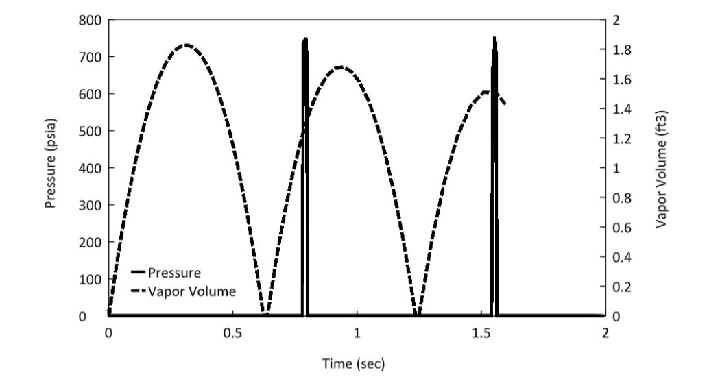
FIGURE 2: Low-pressure area downstream of a fast valve closure, simulated in AFT Impulse™. As flashing occurs, vapor volume grows and eventually collapses, causing sudden pressure surges.
Stress on a pipe and its components due to vacuum conditions and vapor collapse may not be the most critical concern. In many situations, such as treated water or food processing, the process itself is the concern. There is a very little vacuum needed for outside contaminants to make their way inside the pipes. Any leaks in the system which exist under normal positive pressure conditions become locations where contaminants can enter the system under negative pressure conditions. Sterile-process engineers need to really watch out for these conditions.
Learn more at Waterhammer.com
*Article originally published by Chemical Engineering Magazine.