For incompressible hydraulic analysis, an easy way to quantify basic to advanced modeling is the presence and scope of heat transfer. Basic models are isothermal, where the temperature of the working fluid doesn’t change. This makes calculations simpler as the density won’t be altered. The intermediate level would be to introduce heat transfer to a single fluid. One of the most advanced features in AFT Fathom is enabling heat transfer with multiple working fluids in the model. With this feature enabled, a user can use the linked heat exchanger feature allowing two different sub-systems to interact with each other. This article will walk through how to enable multiple fluid heat transfer and then link two heat exchanger objects to represent two sides of the same heat exchanger.
The first step starts where most AFT Fathom models do, Analysis Setup. A temporary fluid must be defined in the Fluid group under Fluid Properties. It is irrelevant which fluid is defined in the Fluid group as the next steps will overwrite it. For simplicity use one of the working fluids or standard water, however, it’s important to not use User Specified Fluid here. With a fluid defined, navigate to the Heat Transfer/Variable Fluids group and select the “Heat Transfer With Energy Balance (Multiple Fluids)” radio button. We’ll return to this menu in a moment, but for now press OK to save the changes in Analysis Setup. If you want to work with multiple fluids or manually alter the properties of a fluid in a pipe without needing to model heat transfer, the Variable Fluid Properties radio button can instead be selected.
Turning on Heat Transfer with Energy Balance for Multiple Fluids fundamentally changes how each pipe will determine what fluid it is working with. Fluid groups now need to be created, then you will assign all of your pipes and junctions to a group to run the model. To create a group, at least one pipe or junction must be placed onto the workspace. The entire network can be drawn out before or after the groups are created. With a single junction or pipe placed on the workspace, make a group by selecting the Edit dropdown -> Groups -> Manager. In the Group Manager menu, select “Create Group” and then give a relevant name for it. A simple option is to name it after the working fluid. To do this, simply create your groups and assign a working fluid to each group.
After creating the groups return to the Heat Transfer/Variable Fluids menu in Analysis Setup. The newly created groups should now appear. By selecting “Use As Fluid Group” next to one of these groups, it can now be assigned a fluid as a working fluid and be applied to the pipes and junctions.
Pressing the ellipsis (…) will open another Fluid menu. Here, select the working fluid from one of the databases or your own defined User Library Fluid. The pressure and temperature used here are defaults, but the model will use the actual temperatures and pressures at their respective points. When utilizing your custom-made fluid from the User Library Fluid, ensure there is data available for Specific Heat, Thermal Conductivity, and Enthalpy for AFT Fathom to solve the Energy Balance equations.
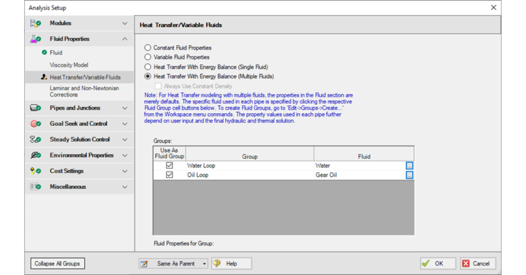
Figure 1: Heat Transfer with Energy Balance (Multiple Fluids) enabled and Fluid Groups Defined.
Now that the groups are created and assigned a fluid, continue and finish defining the rest of the pipe network and junctions. The pipes and junctions now need to be assigned to one of the fluid groups. Return to the Group Manager, highlight one of the existing groups check each pipe and junction that will utilize this fluid, and press OK to save the changes. The changes can be confirmed by going to the Pipe Properties menu and selecting the Fluid Properties tab. It will show what fluid is being used. With these changes, and a defined model, you can press the run button and get results.
With heat transfer enabled, heat exchangers on the Workspace will now have the Thermal Data tab available in their Properties Menu. There are several Thermal Models available, but if you want to utilize the Linked Heat Exchanger option, select one of the following models: Counter-Flow, Cross-Flow, Parallel, or Shell & Tube.
The Link to Heat Exchanger checkbox will be enabled allowing for the second heat exchanger object to be selected, pairing the two together. Paired Heat Exchangers will have an alternating red and blue line between them on the Workspace. The heat transfer out of the fluid from one heat exchanger will be added into the fluid from the other heat exchanger.
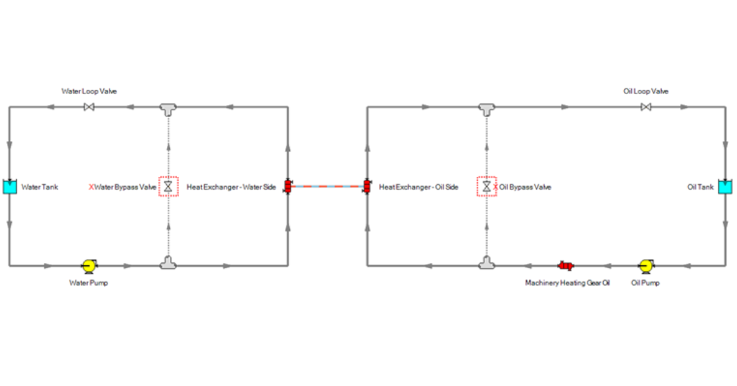
Figure 2: Linked Heat Exchanger.
With the defined model, Fathom can calculate the temperatures in the pipes and determine how much energy is leaving one section for the other through the linked heat exchanger. Applications for this feature range from heating a pipeline in cold climates, cooling air in HVAC, or modeling a steam cooling loop in power generation. Whatever the application may be, give this Linked Heat Exchanger feature a try and let us know how it’s working for you.
ABOUT THE AUTHOR
David Despars is an Applications Engineer. David graduated from Northern Arizona University (NAU) in Flagstaff, Arizona with a Bachelor of Science in Mechanical Engineering and minors in Chemistry, Mathematics, and Music.