AFT Fathom will ensure the pump you select will work in various operating conditions and system expansions
Ben Keiser, Applied Flow Technology Technical Sales Consultant
Hand-calculations to properly size a pump are pretty common. Add the resistances from the piping, components, and fittings as well as system static head to find the total dynamic head the pump needs to provide to deliver the desired flow. So why is it important to use flow analysis software like AFT Fathom when it is easy enough to size a pump by hand?
What about on large systems? Hand calculations are more difficult for complicated systems with significant looping, branching, control features, etc. What about when heat transfer is important? Most of the time in these situations, hand calculations are a best guess that leads to an oversized system with several safety factors… But what if you could size and select your pumps more efficiently for these complicated systems so that you would not need the extra safety factors? You could better ensure that your pumps will consume less energy, operate more efficiently, minimize your life-cycle cost, and significantly decrease repair costs.
When selecting pumps, AFT Fathom makes pump sizing and selection exponentially more efficient. It will take out the guesswork, eliminate error-prone hand calculations and spreadsheets, and will give you solid data and accurate models. As a result, calculation errors are significantly reduced, and you can implement a streamlined sizing process that is easy to apply to different system configurations and can be passed on to other engineers for future expansions.
Would you invest in a software tool simply for streamlined pump sizing and selection?
Of course not. There are many other pieces to the puzzle that must fit together in order to ensure a pumping system operates safely, reliably, and efficiently. In order to maximize uptime and profitability while minimizing repairs, downtime, and energy costs while evaluating the impact of system modifications and troubleshooting operational problems to determine the root cause of an issue, flow analysis software like AFT Fathom is necessary.
A piping system analysis is where the real benefit of AFT Fathom exists. In that regard, proper pump sizing and selection with AFT Fathom involves minimal effort in comparison to what you will really be using the flow analysis software for.
After pumps are sized and selected, the work does not stop there. Different system scenarios should be analyzed. For example:
- determine how pumps operate in different conditions such as varying tank levels
- changes in control valve set points
- differing valve positions, parts of the system being online or offline at different times
- and more
Another important reason for using flow analysis software is when the system configuration changes, such as for an expansion.
At a refinery of a well-known oil and gas company AFT recently visited, one of the senior engineers told me how they recently put two new heat exchangers into service for a small expansion. He asked upper management if they had done a flow analysis beforehand. Upper management stated they decided NOT to do a flow analysis. Sure enough, when they opened the valves to the new heat exchangers, they received little flow because the pumps were already operating at full capacity and serving the rest of the system demands.
THIS is the reason why it is crucial to use AFT Fathom flow analysis software. Not to simply make it easier to size and select the right pumps, but to see if they can operate under different system conditions. If this refinery had decided to perform a flow analysis, they would have determined well-before the system was back online if the new heat exchangers would get the flow that they required.
What should you look for in a hydraulic flow analysis software?
AFT Fathom already includes these features, but if you are looking around, a good flow analysis software:
- Makes it easy to account for heat transfer and the associated thermophysical property changes throughout the system
- Easily handles non-Newtonian fluids and slurries. If viscous fluids are pumped, then viscosity corrections should be considered.
- Allows you to experiment with operating conditions and run multiple scenarios all in one file rather than several independent files that are not connected together in any way.
The system in Figure 1 is an example of a piping network of decent complexity with control valves and heat exchangers in addition to typical fittings and piping. In this example, the desired system flow rate is fixed through the pumps as well as an assumed efficiency and when the model is run, the total dynamic head is determined for the pumps.
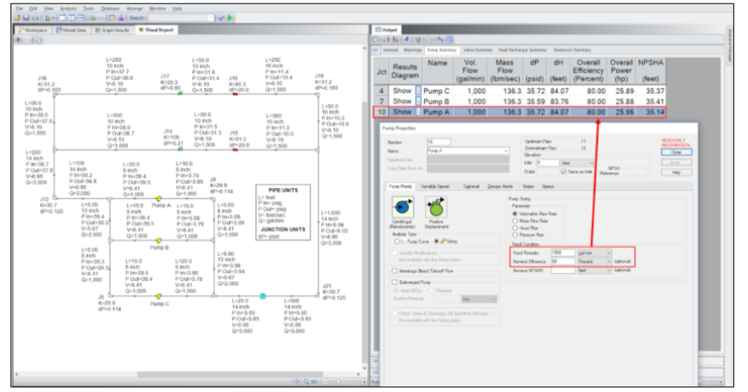
Figure 1 – Sample closed piping system shown including three pumps in parallel with two parallel flow paths with heat exchangers and flow control valves. Results for flow rates, pressures, and velocity displayed on the left with the pump input model and pump results on the right.
After the pump operating point for flow rate, pump head, and Net Positive Suction Head Available (NPSHA) are known, a pump from a manufacturer can be selected. Once selected, the pump curve can be imported rather than using fixed flow rates as shown in Figure 3. You can then verify how the selected pump curve meets the original operating point.
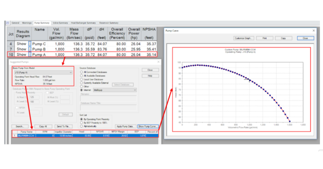
Figure 2 – Pump results for pump head, flow, and NPSH needed to size and select a proper pump with the selected curve displayed on the right.
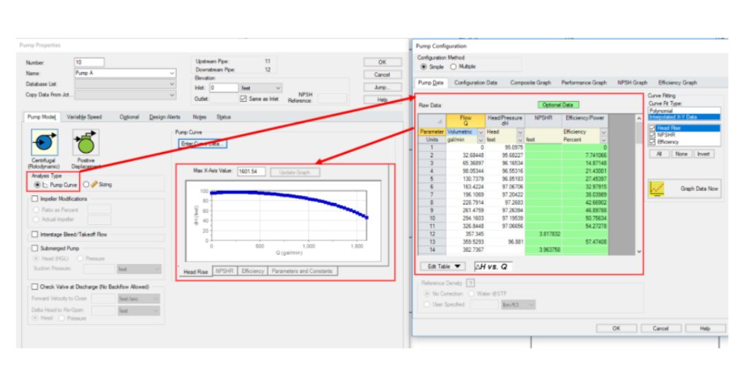
Figure 3 – Pump model shown with the pump vendor’s raw data for the pump curve.
Using AFT Fathom flow analysis software with sophisticated scenario management capabilities, you can easily modify the system with an expansion like that shown in Figure 4. To keep things simple in this example, let’s assume that the expanded system has the same piping characteristics as the existing system. Running the model, one can validate if the system requirements will be met. Results to examine would be to see if the heat exchangers are getting the proper flow rates, determine where the pumps would be operating in relation to their Best Efficiency Points or if they have any NPSH issues, or if the control valves in the system can meet their set points.
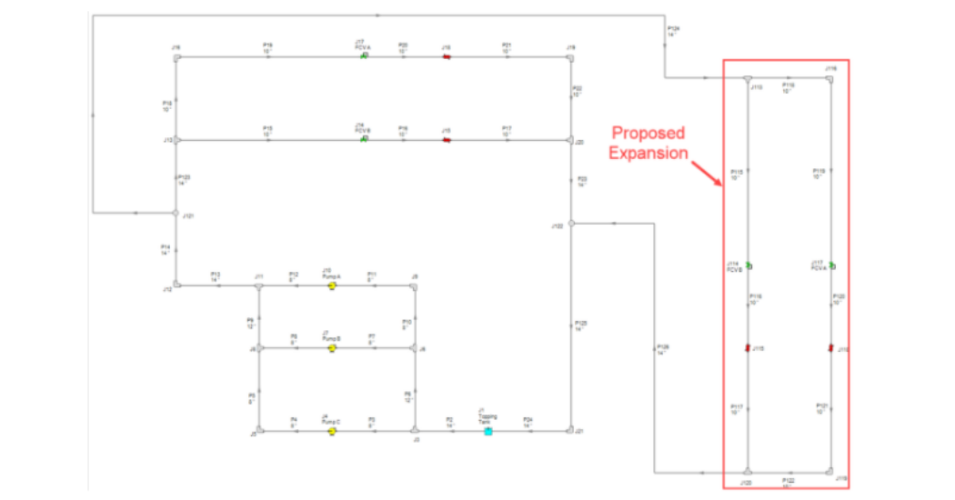
Figure 4 – Original piping system shown with a proposed expansion to the right. The proposed expansion flow paths through the flow control valves and heat exchangers are assumed to be the same as the original system.
With a quick analysis of the results from the system expansion, several issues can be determined that demonstrate the system will not operate as expected. Flow velocities increased significantly due to higher system flow demands. Pumps are operating significantly above their Best Efficiency flow rates. Heat exchangers receive about 30% less flow than that required. None of the control valves can meet their set points and would open all the way to allow as much flow through them as they could.
What do all these severe issues indicate? The pumps as well as the piping system itself are massively undersized for the system with the proposed expansion. It simply will not work, and therefore it is so important to take the time to carry out the flow analysis. However, when you do model the piping system, you can then easily model changes in the system in order to get it to operate correctly.
One thing you might do with the model of the expansion would be to re-size the pumps with the system fully expanded. However, this would be very expensive and not practical. That said, many speak about ways to “optimize” the system operation, but they only focus on the pumps. The system model would very quickly show that simply focusing on the pumps would not provide an optimal solution. The piping system and its complicated interactions matters significantly.
Another approach can be easily accomplished with flow analysis software. Start with a system model that includes a proposed expansion from the beginning of the pump sizing and selection process for the original system design. Certainly, the details and thought of an expansion may not be on the table at this point. However, if the pumps are sized and selected to accommodate larger system flows early on, you can then model scenarios where the expansion flow paths are turned off and perhaps not as many pumps would be needed initially. You could also implement Variable Speed Drives to operate the pumps at different speeds to handle lower flow demands more efficiently. This would reduce the need for control valves that waste significant amounts of energy and cause the pumps to operate away from their Best Efficiency Points. Which would lead to reliability issues, expensive repair costs, downtime, and many other negative impacts.
Planning for a potential system expansion and sizing/selecting the pumps with this in mind would certainly be an easier challenge to overcome rather than learning later the expansion would cause the entire system to not function as needed. Not to mention all the other issues this could introduce.
Overall, using AFT Fathom dramatically streamlines the pump sizing and selection process and allows you to accomplish so much more than typical hand calculations or spreadsheets would allow.
Here are the top 10 features engineers appreciate in AFT software:
1.Multiple Levels of Software Calculation Validation
-
- This can include model comparisons to published examples, an official quality assurance program such as one that adheres to ASME NQA-1 standards for usage in safety related systems in the nuclear industry, and plenty of case studies.
2. Scenario Management
-
- An ability to model any variety of cases within a single model file where you can change any input parameter or fluid properties to determine their effect on results. A “family-tree” like scenario structure is very effective where changes in parent cases should automatically update dependent child cases. An example could be modeling different pump speeds across different scenarios that reflect various operating conditions.
3. Global Editing
-
- Efficiency is important. The ability to massively edit multiple pieces of information at the same time is key. For example, specifying the same pump curve or pump speed for multiple pumps together is easier and more efficient than entering the input component by component.
4. Excel Integration
-
- Importing model changes to multiple scenarios simultaneously makes updating different cases with data variances incredibly effective. Sending specific model output results such as pump operating points and pump and system curve data that a pump manufacturer would need to a spreadsheet format in an automated fashion leads to significant flexibility when carrying out other calculations.
5. Design Alerts for Maintaining Code Compliance
-
- Quickly bring attention to when important parameters are outside their maximum or minimum allowable boundaries.
6. Heat Transfer
-
- Full piping heat transfer calculations should be included to handle convection, buried pipes, layers of insulation, and the ability to calculate external heat transfer coefficients based upon ambient temperatures and windspeeds. Heat transfer through heat exchangers is necessary as is the ability to perform the proper energy balances to determine the mixture temperature when two different streams mix together.
7. Goal Seeking and Transient Modeling
-
- Goal seeking saves great amounts of time by automatically changing multiple input parameters to provide you the results you want. This also aids with model calibration to measured data. Perhaps you might need to vary the pump speed of several pumps in order to achieve a desired flow else-where in the system. Goal seeking automates this process by removing time-consuming manual iteration.
- Transient modeling is important to consider because systems rarely stay the same over time and it is necessary to determine the overall dynamics of a system and how multiple components interact with each other as things change. Simply running multiple cases as a series of steady-state runs would be cause for missing potentially important or problematic intermediate results.
8. Non-Newtonian and Slurry Modeling
-
- A quality flow analysis software should be able to handle not only a wide variety of fluids other than water but should have the ability to handle other types of behavior such as paper stocks, Power Law fluids, Bingham Plastics, or settling slurries.
9. System Cost Analysis
-
- Accounting for the material, installation, maintenance, and energy costs for an entire piping system in an easy-to-read cost report is just as important as determining the system flow, pressure, and temperature distributions.
10. Waterhammer Analysis
-
- Waterhammer situations can lead to disastrous effects upon sudden pressure surges. A quality flow analysis software should have the ability to determine the system pressure response due to various causes like pump trips, valve closures, pump starts, and include the ability to use surge suppression equipment as well.


