The digital oscilloscope has become a crucial testing device for precise voltage signal measurements, gradually supplanting its analog counterpart.
What Digital Oscilloscopes Measure
For oscilloscope testing, digital models offer several cutting-edge features that make them easier to use than their analog ancestors, though there are a few drawbacks. Engineers measure voltage waves with the help of an oscilloscope for testing, substantiating, and correcting circuit designs, though they can also be used to test other electronic components. The waveforms are displayed as an (X, Y) graph (usually with time on the X axis and voltage on the Y axis) representing the measured signal.
This graph illustrates attributes of the signal that include:
- Voltage and time measurements of the signal
- Amounts of DC (direct current) and AC (alternating current) in the signal
- Noise within the signal and whether this noise fluctuates over time
- Periodic signal frequency
- Signal distortion that may indicate a component malfunction
Basically, oscilloscope testing helps the user understand how a signal changes over time, with time represented on the horizontal X axis while voltage is represented on the vertical Y axis.
Advantages of Digital Over Analog Oscilloscope Testing For Bearings
Before the arrival of the digital oscilloscope, testing was done with analog models using CRT screens similar to those used in older televisions. Modern digital oscilloscopes feature flat screens that are less expensive, thinner, lighter, and more energy efficient. Due to these advantages, CRTs no longer feature in any current oscilloscope. Testing with digital oscilloscopes provides an almost identical description of voltage over time compared to analog models.
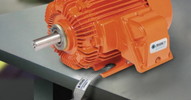
One particularly important advantage of digital oscilloscope testing involves motors running on variable frequency drives (VFDs). Shaft voltage can cause electrical damage to bearings in VFD-controlled motors, causing unplanned downtime due to bearing failure. Often, accurate oscilloscope testing of motor shaft voltage can help prevent this from occurring. It’s best to establish oscilloscope testing early in the operational phase of a VFD-equipped motor, such as after it’s installed or recently repaired.
Accuracy and Precision of Measurements
Testing results are more accurate and precise when comparing a digital to an analog oscilloscope. Before delivery of waveform data, digital oscilloscopes clean up any distortions or other unwanted noise in the measured signal. With higher resolution, digital oscilloscopes can accurately measure both time and voltage. This makes it possible to understand better the risk of bearing failure in a motor.
Processing and Analyzing Signals
When comparing an analog model to a digital oscilloscope, more accurate measurement is but one benefit. More advanced processing and analysis capabilities can be done with digital oscilloscopes. Testing is thus accomplished through the use of several mathematical equations and functions.
Mathematical operations involved in oscilloscope testing include:
- Algorithms like the fast Fourier transform (FFT) for performing a frequency domain analysis
- Augmented triggering selections that capture selected events
- Functions that perform mathematical operations on waveforms
With these capabilities integrated into a digital oscilloscope, testing can incorporate measurements like frequency, peak-to-peak voltage, pulse width, and rise time. Such analysis helps predict more accurately whether and how seriously a motor bearing is at risk of electrical damage.
Recording and Storing Waveform Data
In any sort of oscilloscope testing, the ability to record, store, and replay waveform data makes it more useful. Digital oscilloscopes have more internal memory for data storage, while cloud-based models offer almost unlimited external storage. This permits closer analysis of waveforms while also allowing users to reference a specific reading from an oscilloscope. Testing voltage on motor bearings can thus utilize these saved waveforms for analysis.
Display and User Interface for Digital Oscilloscopes
Ease of use is another factor, with menus in the user interface and often a touch screen featured on a digital oscilloscope. Viewing options include the ability to zoom, pan, or move waveforms easily to focus on particular qualities in the gathered data. These features allow users to adjust the instrument effortlessly, with the simplicity of the process allowing a user to gauge a motor’s shaft voltage or any other signal more effectively.
Limitations of Digital Oscilloscope Testing
While there are many benefits associated with the digital oscilloscope, testing shaft voltage with the instrument does have some drawbacks.
These limitations include:
- Aliasing happens at higher frequencies, occurring when an oscilloscope fails to accurately describe a waveform recording due to not sampling the signal quickly enough, which results in misidentification of the signal frequency; to prevent this, the sampling rate must be double that of the highest frequency part being analyzed
- Constraints on bandwidth can negatively affect the precision of measurements when it comes to higher frequencies; effective bandwidth may also decrease if overly complex signal processing techniques or additional channels are used
- Distortion may occur when the input voltage range is exceeded on a digital oscilloscope; testing some of the stronger signals by digital models is ineffective, though these oscilloscopes tend to have better vertical resolution
- Narrower dynamic range when a digital model is compared to an analog oscilloscope, with testing revealing the extent of signal amplitude readings that describe the system’s range
What is an Oscilloscope Simulator?
Also known as a virtual oscilloscope, these are software applications that simulate the operation of an oscilloscope. Simulators help users better understand how to read the scale screen of an oscilloscope. Simulator software apps also help teach how to test and analyze signals, measure voltage, prototype electrical circuits, check for malfunctions, and conduct other operations by imitating the functions of an actual oscilloscope.
Certain oscilloscope simulators even have capabilities that allow live microphone audio to be used as input signals.
Shaft Voltage Testing With AEGIS® Oscilloscope
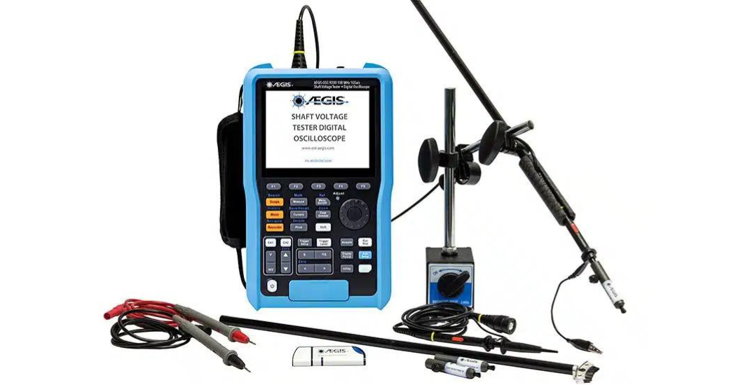
The AEGIS® Shaft Voltage Tester™ Digital Oscilloscope provides maintenance personnel a means to quickly determine when there’s a discharge from a motor shaft that could damage the bearings. With a probe that includes special conductive microfiber tips, each scope also features a USB port for saving readings and a case that makes it easily transportable.
For more information about the AEGIS® Shaft Voltage Tester and how it can help with your application, contact them here.


