By: Ashcroft
Pressure gauges perform an important role in your application, and if they stop working then your entire process can come to an abrupt halt. If you replace your gauge with the wrong one, it can cost you time, money and the safety of your personnel. Replacing your pressure gauge with the most suitable match will ensure that your process can keep operating safely and efficiently. But how do you identify your existing gauge and the replacement that will perform best to keep your businesses operating?
Here are seven questions to ask and the information needed for identifying your gauge. Of course, these aren’t all the factors to consider, but it’s a useful guide to get you started.
1. Case (Enclosure/Housing)
What material is it? Gauge cases are typically available in black-painted aluminum, stainless steel, phenolic, plastic, brass, or another material for meeting an industry specification and/or requirement. In the past, brass was highly preferred as it is extremely resilient for marine applications, though rising costs influenced its replacement by alternative materials. Additionally, 316L stainless steel has become a common requirement for chemical, food and beverage, and sanitary installations.
Next is the case’s structural design. Does it have a solid front or open front? This pertains to whether the gauge does (solid) or doesn’t (open) have an integral wall incorporated into the case behind the dial face. Most gauges do not require a solid front as most are for general pressure measurement, yet it offers additional operator safety and a more rugged enclosure if there are extreme pressure spikes that can lead to the rupturing of the gauge system. The overpressure is projected out of the back of the gauge case and directed away from the operator. Solid-front gauges are common within refineries and chemical plants where there is a heightened concern for process media.
2. Vibration and Pulsation Protection
Another feature often overlooked is whether the gauge is liquid-filled and/or has a throttling device. Why are these important? Each protects the measuring instrument; liquid fill dampens the effects of vibration, whereas a throttle plug/screw dampens pressure fluctuations.
How do you know if these are present? Liquid fill can be verified if the gauge has a solid fill plug and a discernable level of fill fluid typically covering >90% of the dial. Liquid fill protects the gauge movement from excessive wear that otherwise would lead to inaccurate readings and an increase in repair or replacement costs.
Be sure that the selected fill fluid is compatible with the process media – the most common fill fluids are glycerin, silicone or halocarbon. You can see if a unit has a throttling plug/screw installed by looking into the process port, which is used to keep process pulsation from affecting the gauge.
3. Contamination Control
To replace your gauge, be sure to confirm that the wetted material of the pressure system is fully compatible with your process media. Often, the pressure system’s wetted materials are printed on the dial face and/or on the gauge socket. This corrosion guide can assist in your selection process!
4. Accuracy
Check the gauge face (dial) of your gauge. How many graduations and figure intervals are there? This will help verify gauge accuracy. Most gauges meet either ASME B40.100 or EN 837-01 – both standards guide the number of dial graduations and figure intervals.
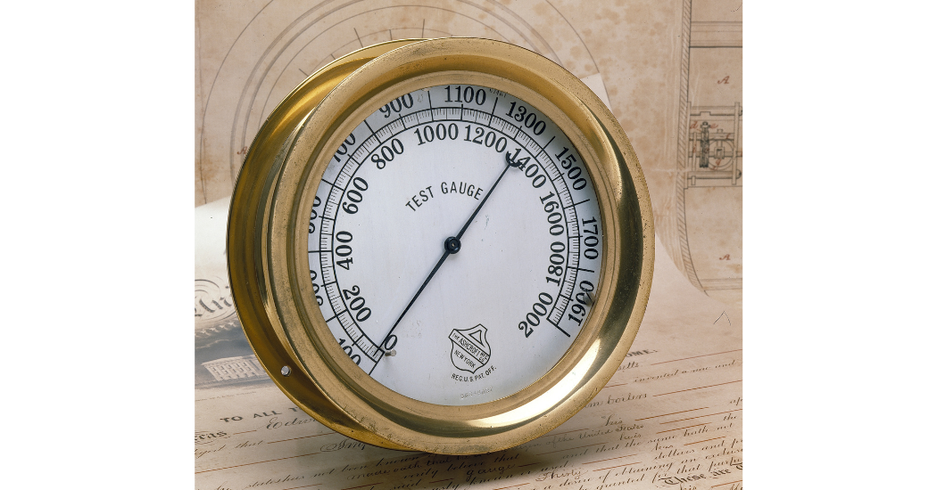
Remember, a greater number of graduations/figure intervals means higher instrument accuracy. Also, units with a mirror band running along the dial’s edge are typical of test gauges, and they will also have a fine “knife-edge” pointer.
5. Connection Size
You will soon realize that pressure gauges offer a wide variety of pressure connections. The most common standard for the U.S. is NPT (National Pipe Thread). You should know the thread type to ensure proper installation and prevent potential damage due to galling or cross-threading.
As a rule, the size of the gauge dial is a guide to understanding the common pressure connection size. Economical gauges with 1 ½ to 3 ½ in. dials typically offer 1/8 NPT to 1/4 NPT, while 4 ½ in. or larger dial sizes offer 1/4 NPT to 1/2 NPT. Models identified as process gauges have dial sizes of 4 ½ in. and larger and are commonly supplied with a 1/2 NPT that supports the instrument.
6. Connection Location
Where is the mounting location on your instrument? Is it lower or back/rear connected, or does it have a special orientation such as 3, 9 or 12 o’clock? Additionally, you should be aware of space restrictions that will limit installation.
When replacing your gauge, consider these mounting options:
- Stem mount: offered with a lower connect gauge
- Wall/surface mount: offered with a lower connect gauge
- Panel mount: offered with a back connect gauge
- U-clamp flush mount: offered with a back connect (panel mount installations) gauge
- Front flange flush mount: offered with a back connect (for panel installations) gauge
7. Pressure Ranges
Confirm the dial pressure range and units of measure of your gauge. This should also help identify the accuracy as mentioned under step 3. When replacing the gauge, consider that ASME B40.100 recommends normal operating pressure be confined to 25% to 75% of the selected range. However, in the event of pulsation, the maximum recommended operating pressure should not exceed 50% of the full-scale range.
Learn more about what you need to consider when replacing a gauge here:
https://blog.ashcroft.com/identify-your-pressure-gauge?utm_source=EmpoweringPumps


