Author: Heinz P. Bloch, P.E.
There is a widely overlooked item on sliding supports: Steel-Teflon®-Steel is not usually a satisfactory sliding support for the true reliability professional. The steel plates (“shoes”) will oxidize and, due to surface roughness, will dig into the Teflon. Best practice is to use Steel-Teflon®-Teflon®-Steel, in which case Teflon® will slide on Teflon® with considerable ease, providing long-term satisfactory sliding action.
At the 2017 TAMU Pump Users’ Symposium, an attendee asked why for over a hundred years pump piping continues to be pulled into place for final match-up to pump nozzles. My answer had to do with users being unwilling to listen to Best Practices implementers and a refusal of folks to read the instructions the reliability-focused have been trying to put into their hands. But remember: There is no value in owning a book and then not reading it. The one who owns a book yet doesn’t read it is no different from an illiterate person. Harsh-sounding words — but true nevertheless.
Best practice requires installation of piping from vessels or other structures upstream of the pump and towards the pump suction nozzle, to a point at most 10 ft (3 m) from the suction nozzle. Then, one places a pipe flange at the suction nozzle and works toward the pipe run that had been terminated 8, 10, or at most 10 ft away. The same work sequence is utilized on the pump discharge piping (Ref. 1).
Upstream and downstream of the process pump, the final connections are then made either at gasketed pipe flanges or by welding. While making these final connections at both upstream and downstream terminations 8-10 ft from the pump, dial indicators set up to monitor pump nozzle and bearing housing movement must not show displacements in excess of 0.002 inches (0.05 mm). Yes, the additional weld costs money, but the payback is nothing short of remarkable. Reliability does not drop into the laps of laggards and know-it-alls. Achieving safety and reliability requires effort.
Monitoring pipe stress while bolting up
Pumps are designed to allow only limited loading of pump suction and discharge nozzles. Misaligned pipes can produce forces and moments on pump nozzles that vastly exceed maximum allowable values. Excessive piping loads can cause high vibration, shaft misalignment, seal distress, bearing overload and coupling failures. If you think you’re OK because you get 3 years’ life from your bearings or mechanical seals, think again. If your competitor (by doing things right and spending $25 on a book) gets 6 years before having to replace bearings or mechanical seals, his maintenance expenses are one one-half of yours. Professionals read books; Bubba disdains book and only listens to anecdotes. While there’s a smidgeon of truth in most anecdotes, compare it to a garbage can with one good piece of candy in it. Some wouldn’t go near it, others dive for the one good piece. Which begs the question: Should we spend time doing things right the first time or should we go for lots of trial and error attempts that leave safety and reliability on the back burner? We clearly have choices to make……
Back to our topic: To keep within allowable limits, several dial indicators are set up to monitor the pump’s sensitivity to pipe stress. Dial indicator movement is monitored while initial and final bolt tightening is in progress. Four dial indicator stems are set to contact pump and driver feet to detect unsupported (soft-foot) conditions; two additional dial indicators observe the pump bearing housing for movement in the x and y-directions. Any indicator needle displacement in excess of 0.002 inches (0.05 mm) will require corrections to the piping. Trust me: 0.002 is routinely achieved by good maintenance technicians. The not-so-good ones argue if this kind of accuracy is really needed.
Again, a process pump should never be allowed to serve as a pipe support. Chain-falls or come-along hoists and other supplementary mechanical tools (pulling devices) are never allowed or used by competent and reliability-focused pump installation crews (Ref. 2).
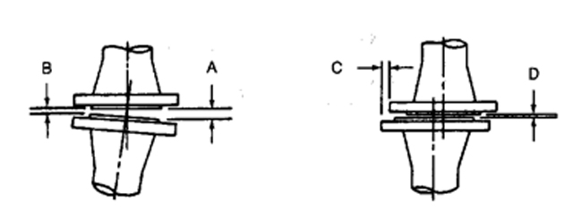
In general, maximum misalignment pipe flange to pump nozzle and flange-to-flange should be kept within the limits of Fig. 1. Before allowing connections to be made, the two mating faces should be
- Parallel with each other within 1/32 in. (0.8 mm) at the extremity of the raised face, i.e. “A” and “B” in Fig. 1 should differ by no more than 1/32 in (0.8 mm)
- Concentric so their centerlines coincide within 1/8 in, i.e., the offset “[C minus D]” should not exceed 1/8 in (3 mm).
SEE FIGURE 1 AT THE TOP
There are two important, simple, yet very useful tests:
- It must be possible for an average-size worker to push the misaligned piping into place with his two hands, without using any supplementary mechanical tools
- Once the gasket has been inserted and the bolts have been torqued up, dial indicators observing the upwards and sideways motion at the pump suction and discharge nozzles cannot move in excess of 0.002 inches (0.05 mm) in any direction.
References
- Bloch, Heinz P. and Allan Budris; “Pump User’s Handbook: Life Extension,” 4th Edition, (2014), Fairmont Publishing, Lilburn, GA, ISBN 0-88173-720-8
- Bloch, Heinz P.; “Pump Wisdom: Problem Solving for Operators and Specialists”; (2011), Wiley & Sons, Hoboken, NJ; ISBN 9-781118-04123-9
- Bloch, Heinz P.; “Petrochemical Machinery Insights,” (2016) Elsevier Publishing, Oxford, UK, and Cambridge, MA, ISBN 978-0-12-809272-9
Why Pumpsets Should Not Be Installed in “As-Shipped” Condition


Comments