Author: Heinz P. Bloch, P.E.
At the risk of stating the obvious: Let’s be sure the lubricant in a pump’s bearing housing is kept clean. Even the most outstanding lubricant or lube application method cannot save a bearing unless the oil is kept clean. This is where bearing housing protector seals are of value (Refs. 1 through 3).
Lubricant contamination originates from a number of possible sources and can also be a factor in “unexplained” repeat failures. Unless process pumps are provided with suitable bearing housing seals, an interchange of internal and external air (called “breathing”) takes place during alternating periods of operation and shutdown. Bearing housings “breathe” in the sense that rising temperatures during operation cause air volume expansion, and decreasing temperatures at night or after shutdown cause air volume contraction. Open or inadequately sealed bearing housings promote this back-and-forth movement of moisture-laden and dust-containing ambient air. Please note, simply adding bearing protector seals could change windage or housing-internal pressure patterns in unforeseen ways. This, too, we must recognize as a potential source of “unexplained” failures in housings without internal balance holes. Moreover, different pressures could cause oil “weepage” past a seal and along the shaft.
Breather Vents. Ideally, housings should not invite breathing and the resulting contamination. There should be little or no interchange between the housing interior air and the surrounding ambient air. The breather vents used in millions of pumps can often be removed and plugged. Don’t be shocked by that statement. Many hundreds of millions of refrigerators and automotive air conditioning systems operate with neither vents nor breathers.

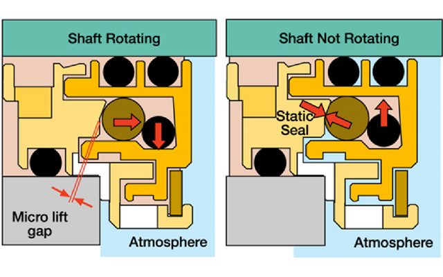
Figure 1: Visualizing component damage risk. Although the sketch above does not replicate an actual product, it conveys what can happen with bearing protector seal designs that incorporate sharp-edged grooves. The actual photo on the bottom is from a similar bearing housing protector seal; pay attention to what it is we are buying.
Beware: Some old-style bearing housing seals allow an O-ring to contact an O-ring groove, as depicted in Figure 1. Contact with sharp-edged grooves invites dynamic O-rings to scrape. That’s another disclosure which should not shock us; none of us would think that sliding our fingers over a knife is without risk.
Abraded elastomer shavings from bearing housing protector seals of the type illustrated in Figure 1 can contaminate the lubricant and cause oil to change color. Also, using only a single O-ring for clamping the rotor to the shaft makes the rotor less stable than if two rings are used for clamping duty. Visualize rotor instability by mentally removing the stationary component in Figure 1. The rotor pivots around the clamping O-ring and destructive vibration would occur at high speeds. We could study the rotor dynamics of such a situation and spend a nice sum on doing research, or we might reach the same conclusion by giving it some thought. Two clamping O-rings will provide more stability than one single clamping O-ring.
In essence, bearing housing protector seals can greatly improve both life and reliability of rotating equipment by safeguarding the cleanliness of the lubricating oil. However, these protector seals add little value if (1) oil contamination originates with oil ring wear, (2) if pressure-unbalanced constant level lubricators are used that allow air and moisture to intrude, (3) if the oil is not kept at the proper level, (4) if the bearing housing design disregards windage concerns, or (5) if water enters into the oil.
We know all about see-through containers sold for installation at the bottom of the pump bearing housing. However, the physical processes of water-in-oil are working against us, and using these “sludge cup containers” is misleading. By the time water becomes visible in such a “sludge cup container”, the saturation limits of oil-in-water will have been exceeded, and much damage could have been done to the bearings. We can deduce that free water in the oil is a symptom of not having the right bearing housing protection. Our reliability focus should be on treating the root cause, not the symptom. We should prevent water from reaching the bearings in the first place. These proactive and precautionary thought processes are at the core of pump failure prevention.
Ranking the different lube application practices
Although oil ring lubrication is widely used, it is relatively maintenance-intensive and ranks last from the author’s experience and risk reduction perspective. Next, flinger discs have been used for many decades and allow operation at higher DN values than oil rings. Because they are firmly clamped to the shaft, there is far less sensitivity to installation and maintenance-related deviations. On the other hand, non-clamped push-on flinger discs were tried a few decades ago, and with very disappointing results. API-610 therefore disallows push-on flingers and some other low-cost oil application components.
Plant-wide oil mist lubrication systems are ranked ahead of flinger discs. Oil mist has proven superior to conventional lubricant application since the late 1960’s. Pump bearing failure reductions ranging from 80 to 90% have been reported by Charles Towne of Shell Oil, and many others (Miannay, 1974; Shamim and Kettleborough, 1994; Shamim and Kettleborough, 1995; Ehlert, 2011). Charles Towne performed tests on identical process units at Shell Oil and deserves much credit for his seminal work on the subject.
The highly beneficial in-plant, real-life results reported by Towne (Shell Oil) refer to pure oil mist, not purge mist. Pure oil mist is an oil-air mixture with a volumetric ratio of 1:200,000. The oil is atomized to globule form and carried by the air, applied in modern plants as shown in Figure 3. The same illustration, Figure 3, could also be used to depict liquid oil spray. Liquid oil spray is sometimes called “jet oil” lubrication.
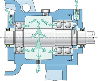
Figure 3: Oil mist lubrication applied to a pump bearing housing in accordance with API-610, 11th Edition With oil spray lubrication, liquid oil would enter at the nozzles. Note the dual mist (or, for spray lube application, dual liquid oil) injection points. Observe dual-face magnetic bearing housing seals that prevent oil mist (or oil spray) from escaping to atmosphere.
In Figure 3, and with either oil mist or oil spray, there would be no oil rings, flinger discs, or constant level lubricators. Because the mist (or spray) application nozzles shown here are relatively close to the bearings, oil mist flow or the stream of liquid oil will overcome windage. While this jet oil or oil spray lube application method seems like a bold idea, the method is extensively documented by MRC and SKF, also in all three of our reference texts. This lubrication method is very often used in high performance aircraft and we certainly did not devise it. We simply know that it works best. As to Fig. 4, the author is simply trying to show that oil pumps located inside a bearing housing are not a novelty. We have seen them in small and medium-size steam turbines for close to 100 years. They are reliable and long-lasting. We can conclude that:
- The duty imposed on self-contained oil spray pumps (a small pump inside the bearing housing of a process pump) would be quite benign compared to other known, reliable, shaft-driven pumping technologies or services
- Oil filtration would be very easy
- The elimination of oil rings and constant-level lubricators would be a very positive reliability improvement step
- Part of the energy requirement of an oil application pump would be re-gained in the form of reduced bearing frictional losses
With spray lubrication, much needed oil application innovation would benefit the drive end and thousands of repeat failures of pumps would no longer occur. However, as of today, little interest has been shown by manufacturers and users to redesign pump bearing housings. That’s very disappointing, and a real loss.
The market drives these developments. Accordingly, if buyers and pump owners tolerate repeat failures and the manufacturers benefit from the sale of spare parts, it will be business as usual. Still, and at the risk of stubbornly bucking the trend: As responsible engineers, we should advocate changes in mindsets. As a realist, the author is under no illusions as to where some users and manufacturers will be when the dust settles: We will never convince or even reach some of them. All we wanted to do is explain matters to those whose reliability focus extends beyond “business as usual” and who are interested in pushing for lower-risk oil application alternatives.
That said, one of the most straightforward ways to drive a housing-internal oil pump could be modeled on the right-angle worm drives typically found in small and medium-size steam turbines. While the arrangement shown in Figure 4 is associated with a mechanical governor, it is but one of many highly reliable options that merit consideration for small oil pumps that take suction from the process pump’s oil sump, pressurize (and perhaps filter it) and then spray this oil into the pump bearings.
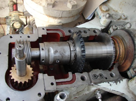
Figure 4: Drive arrangements similar to the highly reliable mechanical governor drive in this small steam turbine are suggested for bearing housing-internal spray-lube oil pumps in process pumps
Recall again that all bearing manufacturers consider spraying liquid oil into the rolling elements the best possible lubrication method. Every bearing manufacturer the author has worked with in the over five decades since 1958 has ranked an oil spray (liquid “oil jet”) ahead of oil mist lubrication and far ahead of oil rings (slinger rings). That’s a compelling fact which should not be ignored.
Conclusions
Many process pumps continue to experience costly repeat failures. Motivated reliability professionals and informed users can avoid these and will appreciate recommendations on failure risk reduction. For the truly reliability-focused pump users, a number of conclusions and upgrade recommendations may be of interest:
- Discontinue using maintenance-intensive oil rings and, if possible, constant level lubricators.
- As a matter of routine, the housing or cartridge bore should have a passage at the 6 o’clock position to allow pressure and temperature equalization and oil movement from one side of the bearing to the other.
- With proper bearing housing protector seals and the right constant level lubricators, breathers (or vents) are no longer needed on bearing housings. The breathers (or vents) should be removed and
- If constant level lubricators are used, a pressure-balanced version should be supplied and its balance line should be connected to the closest breather port.
- Bearings should be mounted in suitably designed cartridges and loose slinger rings (oil rings) should either be avoided or, in some high DN cases, disallowed. D = shaft diameter in inches, N is the shaft RPM. If D is 2.5 inches and N=3,600 RPM, then DN= 9,000. That is too high for allowing the oil level to go through the center of a bearing ball at the 6 o’clock position.
- Suitably designed flinger discs should be secured to the shaft whenever the oil level is lowered to accommodate the need to maintain acceptable lube oil temperatures (i.e., for pumps operating with DN-values in excess of 6,000). In this convention, D = shaft diameter in inches, N is the shaft RPM. If D=2 inches and the pump shaft turns at 1,800 RPM, DN=3,600 and it’s OK to let the oil level reach the center of a bearing ball at the 6 o’clock location.
- Modern and technically advantageous versions of bearing housing protector seals should be used for both the inboard and outboard bearings. Lip seals are not good enough, and neither are outdated rotating labyrinth seal designs.
Knowledgeable engineers can show that some widely accepted pump components tend to malfunction in the real world. Moreover, as industry often moves away from solid training and from taking the time needed to do things right, designing-out risk and designing-out maintenance become attractive propositions.
References
- Bloch, Heinz P. and Allan Budris; “Pump User’s Handbook: Life Extension,” 4th Edition, (2014), Fairmont Publishing, Lilburn, GA, ISBN 0-88173-720-8
- Bloch, Heinz P.; “Pump Wisdom: Problem Solving for Operators and Specialists”; (2011), Wiley & Sons, Hoboken, NJ; ISBN 9-781118-04123-9
- Bloch, Heinz P.; “Petrochemical Machinery Insights,” (2016) Elsevier Publishing, Oxford, UK, and Cambridge, MA, ISBN 978-0-12-809272-9


Comments