Author: Michael Huebner, Principal Engineer, Flowserve
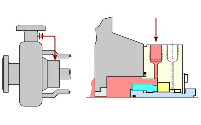
Mechanical seals generate heat during operation due to mechanical friction and fluid shear between the seal faces. One of the most common strategies to remove this seal generated heat and create a cooler environment in the seal chamber is through a Plan 11. A Plan 11 directs process fluid from a high-pressure region of the pump through a flow control device, through the seal chamber, and back into the process. Sizing the flow control device is a critical parameter in setting up this system.
The flow rate of a Plan 11 is determined by the differential pressure between the starting point (e.g. pump discharge) and the ending point (e.g. pressure downstream of the seal chamber) of the fluid flow as well as the restrictions in the system. The most common flow control device is an orifice due its simplicity. It is a common industry practice to use an orifice with a diameter of 3mm (or 0.125”) or greater to minimize the potential for plugging due to debris in the process fluid. In many cases, it is necessary to use more than one orifice due to a high differential pressure in the Plan 11 system. In some cases, other flow control devices such as a pressure breakdown coil may be required.
Flow through the Plan 11 will also be influenced by a throat bushing in the back of the seal chamber. This may be desirable especially if there is a benefit in increasing the pressure in the chamber. The most common throat bushing (e.g. fixed bushing provided by pump OEM) will have little impact on the flow or pressure in the Plan 11 due to the clearances. If a bushing is required to control flow or raise pressure, it must be specifically designed and analyzed for the application. This will normally require a floating, close-clearance bushing.
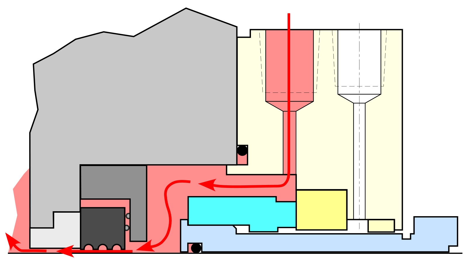
Throat bushing in seal chamber
In a normal Plan 11 system, the orifice sizing almost exclusively determines the flow through the system. Other elements such as tubing size, tubing length, or number of or fittings have much less of an influence. Even the use a single point injection or distributed flush will have far less of an impact on flow than the orifice sizing. Seal OEMs can help provide guidance on the required flow rate and specifications for the components in a Plan 11 for specific applications.
As the Oil and Gas Industry Strengthens, New Challenges Emerge

Comments