Author: Ray Hardee, Engineered Software Inc.
A plant engineer used a piping system model to determine why his facility’s large cooling water system had not been operating properly. After building the piping system model to reflect the design of the installed piping system, the engineer discovered the installed system was not operating as described in the physical model. Further investigation revealed that the throttle valves were fully open in all flow circuits, which resulted in a flow rate through the entire system that exceeded the capacity of two cooling water pumps operating in parallel. This forced the plant to operate three pumps in parallel; but rather than continue to run three pumps in parallel with higher flow rates through each circuit, the plant engineer decided to balance the system by positioning the throttle valve to achieve the design flow rate through each circuit.
The system operation was reviewed after balancing, and it was discovered that two circuits within the system did not have sufficient flow rates to maintain the outlet temperature of the cooling load. The immediate objective was to operate the plant to meet the production requirements, so the flow rate through the two problem circuits was increased. The plant engineer was not completely satisfied with the result of increasing the flow rate through the two problem circuits, so he set out to troubleshoot and pinpoint the problem.
Troubleshooting Problems with Two Heat Exchangers
The plant engineer began by focusing on why the two circuits in question could not maintain the outlet temperature with the design flow rate. He was presented with two possible reasons for the difference:
- There were problems in heat exchangers in the two circuits that are not operating as designed.
- The established engineering principals of heat transfer for some reason do not apply to only these two heat exchangers within this particular system.
Because the same engineering principles apply to all heat exchanger operation, the plant engineer focused on the problem with the heat exchangers.
After talking with the heat exchanger manufacturer, the plant engineer discovered the system design data needed for sizing a heat exchanger. Figure 1 shows the various items found in a heat exchanger, which transfers thermal energy from the primary side fluid to the secondary side fluid.
The first requirement for sizing a heat exchanger is to calculate the heat transfer rate needed by the process fluid. The heat transfer rate of the process system is a function of the mass flow rate of the process fluid, the specific heat capacity of the process fluid and the differential temperature of the process fluid. Equation 1 below describes the process in detail.
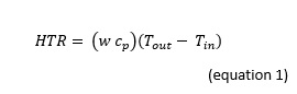
HTR = heat transfer rate in BTU/hr
w = mass flow rate in lb/hr
cp = average of the specific heat capacity from the inlet and outlet fluid temperatures in BTU / (lb (o)F.
T out = fluid temperature at the outlet of the device in (o)F
T in = fluid temperature at the inlet of the device in (o)F
Like all types of energy, the thermal energy removed from the primary side must balance with the thermal energy added to the fluid in the secondary side. Using this engineering principal we can use Equation 1 to determine the requirements for the cooling water side, to meet the heat transfer requirement of the primary side.
The heat transfer fluid on the secondary side is water, which provides us with the value for fluid specific heat capacity. When designing a cooling system, it is common practice to have a common design inlet temperature for the entire system. In addition, the cooling water system is typically designed for a consistent temperature across each heat exchanger.
Knowing that the heat transfer rate for the heat exchanger’s process side and cooling side must be equal, we can use the secondary sized temperature and the required heat transfer rate to determine the mass flow rate through the secondary side of the heat exchanger.
With this information, the manufacturer can provide a heat exchanger design to meet the systems heat transfer rate. Without going through the engineering details of designing a heat exchanger, the manufacturer provides the plant engineer maximum thermal capacity available for the heat exchanger consisting of the heat transfer surface area, the maximum heat transfer coefficient for the clean heat exchanger design, and a specified fouling factor. Equation 3 below shows the UA available for a specific heat exchanger.
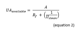
Where:
UA available = maximum thermal capacity of the heat exchanger BTU/hr / (hr-F°
A = heat transfer surface area as specified by the manufacturer ft2
U clean = maximum heat transfer coefficient of a clear heat exchanger BTU/(hr x ft2 x °F
Rf – fouling factor based upon heat exchanger design requirements.
In Equation 2, there are two terms that can affect the operation of the heat exchanger. If a leaking tube is plugged in the heat exchanger, this will cause a reduction in tube surface area. Fouling of the heat exchanger tubes with dirt, oil, or mineral deposits affect the heat’s ability to flow through the heat transfer tubes. The heat exchanger is designed with a given fouling factor Rf, and when this value is exceeded the UA available for heat exchanger is reduced. A reduction in the heat exchanger’s UA value will require a higher flow rate to transfer the same amount of heat.
Getting to the Root of the Problem
Using this knowledge, the plant engineer started looking into the problem with the two circuits with excessive flow. In checking the maintenance records of the two heat exchangers in question, it was discovered that none of the internal tubes were plugged, and as a result, the surface area of heat exchanger tube sheet was not affected. Looking at the maintenance records for the two heat exchangers in question, the engineer discovered that these heat exchangers had not been cleaned in more than three years. As a result, a work order was issued to clean the tube sheets during the next planned outage.
As you can see from this example, the piping system model can provide a wealth of accurate data of how the system should operate. Using that information, the plant engineer was able to troubleshoot the operation of equipment that was not operating as originally intended.


Comments