
Author: Dominik Fry, P.E., Engineered Software, Inc.
Plant processes have become more intricate with a host of supervisory control and data acquisition (SCADA) solutions to achieve the precision control necessary to deliver a finished product. Control rooms have upgraded from analog to digital, with displays giving the operator data.
Operators can now tell which pumps are operating, various tank levels, concentrations, flow rates and much more. This is great for operators trying to hit a certain target. It can be tough on the health of the system. When there are issues, pinpointing the broken equipment is easy. However, determining the root cause of the problem is much harder.
Determining how a system interacts can be difficult. Processes and components change as upgrades are implemented over time. The new Department of Energy (DOE) standards for pumps and new motors are a challenge for the entire pumping industry. You cannot simply swap out an old motor for a new one anymore. There are operational challenges such as different-sized baseplates on new motors. There are also elements that change how the system will work, such as startup current, horsepower (hp) and slip.
With a more efficient motor, you could potentially have higher energy costs due to a higher pump speed. Now figure into the mix all the tweaks the operator is making and ask: Is your system really working smarter? Just because a control room looks high tech does not mean the underlying system is functioning as designed.
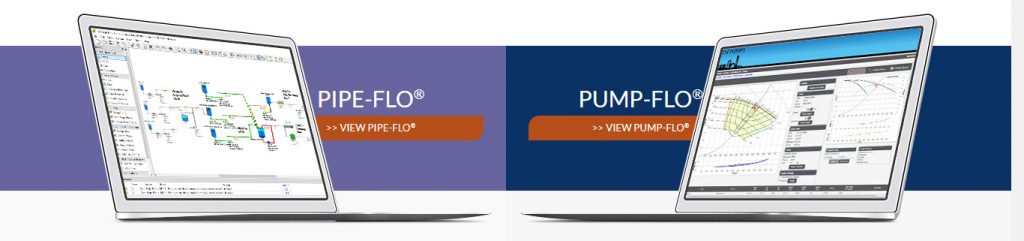
Fluid flow software provides a clear picture of how a piping system operates by calculating the flow rates and pressures in the system. Initially, this software was mainly used to design the piping system, but recently, more plant personnel are using this software to simulate the operation of existing fluid piping systems.
1. PAINT A TOTAL PICTURE
To be effective in the plant operating market, the fluid flow software provides the user with enough information to design, build, operate and maintain the system throughout the plant’s life. This will show the conditions or positions to achieve a certain set point and the effects on the entire system. A valve position may change for a lower set point, but this may trigger warnings if it makes the pump run outside its acceptable operating range, or if minimum or maximum flow velocities are exceeded.
2. VISUALIZE CONNECTIONS
Providing the user with a clear picture of how the items in a piping system are connected is a must. Piping schematics show the connection between location of tanks, pumps, components, control valves and pipelines. A piping schematic identifies each item in the system using the project’s equipment naming convention.
3. CALCULATE FLOW RATES, PRESSURES
Fluid flow software calculates the balanced flow rates and pressures in piping systems. It can handle open- or closed-loop systems, as well as series, branching and parallel flow paths. Sizing rules and design limits assist the user in optimizing or warning for individual pipelines during the design process. Set up and save various operating scenarios so the user can see how the system operates under a variety of expected operating conditions.
This approach also allows the user to optimize the piping system as it is being built, providing a better final design. Using these calculation techniques, the user can quickly build the piping system model without having to get involved with the program’s inner workings.
4. COMMUNICATE SPECIFICATIONS
Communication is necessary to ensure the various groups involved in the project have a clear understanding of how the piping system is to be built and operated. To ensure a system is built to meet the requirements of the end user, specification documents are developed outlining the methods for each item’s design, construction and testing.
During the design process, the information must be checked and reviewed by other members of the design team. After the system design is completed, the owner of the piping system must review the information. The ability to communicate with others ensures everyone involved with the project has access to all the information needed to design, build, operate and maintain a fluid piping system.
5. BUILD THE SYSTEM MODEL
Building the system model involves entering the details about each item in the piping system. Much of the information needed to build the model is obtained during the design process. It is always best to create the model during the design process and keep the model current through construction and startup. This allows users to turn over a completed piping system model to the client as part of the required design package.
Read the rest at Engineered Software’s blog!

Comments