Author: Heinz P. Bloch, P.E.
Many pump manufacturers have compiled recommendations on pump maintenance which vary from one manufacturer to the next. They generally differ among pump types and models, yet, there are some common threads or essentials to be considered.
Superior maintenance requires upgrading
Suppose there was a design flaw, or some other hidden, elusive issue that is responsible for causing repeat failures, short run lengths of a pump, or whatever. More than traditional maintenance effort may be needed, which gets us to the subject of superior maintenance. Superior maintenance is a reliability improvement task. The best-performing or Best-of-Class companies are not repair-focused; they are reliability focused. These are companies that have given some of their personnel the task of determining if upgrading to a better component or better system is feasible.
If an upgrade is feasible, the contributor is asked to calculate its cost. A best-performing company would then ask what this upgrade effort will be worth, perhaps in a simple benefit-to-cost or payback estimate.
A good example involving upgrade issues would be Figure 1. The “cooling fan” in the left illustration is simply too small to be of any value. The well-dimensioned fan shown on the right will probably be very effective. Please note, however, that applying cooling only to bearing outer rings may be counterproductive. Cooling applied to the outer shell may not affect the hot inner rings. As these thermally expand, internal clearances may vanish and cause excessive bearing preload. These load increases will then reduce bearing life.
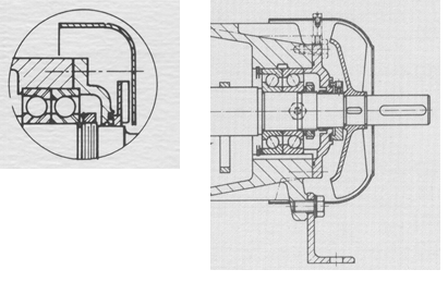
Fig. 1: Ineffective “cooling fan” (left) and a reasonably effective fan (right)
Suppose an effective fan was used. In that case, the entire design must be reviewed for pressure differences surrounding the bearings. These differences might affect lube oil flow or oil level conditions in the adjacent bearing set. Therefore, many bearing housings must be upgraded to reduce failure risk. The best course of action would be to discard both of the two fans in Figure 1. Also, it would be prudent to
- implement means of pressure equalization across the thrust bearing set
- use an appropriate synthetic oil
- consider the various shortcomings of oil ring(s)
- question, and then verify, the axial load capacity of the snap ring in the housing bore shown on the right side of Figure
Impeller upgrading with inducers
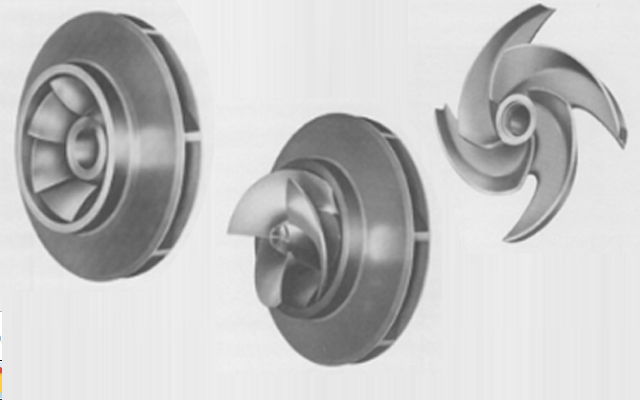
Three of the many thousands of impeller configurations and geometries available are illustrated in Figure 2 (at the top). Closed and open impellers are available; an inducer-type impeller is shown in the center of the picture.
Inducers are often custom-designed for a particular pump application. They lower the NPSHr of an impeller, but do so only in the vicinity of best-efficiency flow (BEP). If pumps with inducer-equipped impellers are operated at flows substantially above or below BEP, their NPSHr may actually increase compared to that of a standard impeller not so equipped. Instead of the continually increasing slope of the NPSHr curve typically shown on a manufacturer’s performance curve, the NPSHr curve associated with an inducer would probably have a distinct U-shape.
Distance from impeller tip to stationary internal casing components
Any particular process pump is designed with a casing which, of course, surrounds the pump rotor. For this rotor and its impeller to turn freely while, at the same time, accommodating a certain amount of shaft run-out and shaft deflection there needs to be a rather liberal impeller-to-casing clearance.
In practice, one makes a distinction between two different gaps shown in Figure 3: Gap “A” and Gap “B”. Gap “A” is the distance from the impeller disc and cover peripheries (the cover is sometimes called a shroud) to the nearest casing or other stationary part. That stationary part is usually the tongue, or cutwater. Some pumps are designed with casing internals called diffuser-style or vaned, others are simply an unimpeded stationary passageway for the fluid leaving the impeller. Regardless of casing-internal construction, a gap of 50 mils (0.050 inches or 1.2 mm) is chosen for best possible efficiency and so as to minimize leakage-induced flow turbulence.
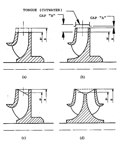
Fig. 3: Gap designations and impeller trim methods, including vane tips only (left); across entire outside diameter (center); oblique cut (right), based on Ref. 1
Gap “B” is the average distance from the impeller vane tips (the diameter D’) to the casing-internal stationary part where the fluid coming off the impeller vane tips enters a stationary passageway. This part of the stationary passageway is usually called the cutwater, or volute tongue. Recommended (radial) minimum, maximum, and preferred values for Gap “B” are given, in Table 1, as a percentage of the impeller radius. In large pumps (typically pumps with drivers in the over 250 kW range) too small a gap will often increase vibration amplitudes, whereas too large a gap will result in a loss of efficiency.
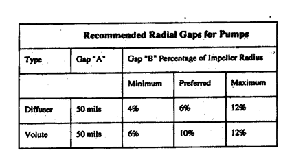
Table 1: Recommended radial gaps for process pumps
As an alternative to Gap “B” modifications, volute chipping—the removal of a small amount of metal from the tongue or cutwater—is sometimes feasible (Ref. 1).
Impeller trimming
Virtually every textbook on pump engineering contains guidelines on impeller diameter reductions or “trimming” needed to permanently affect the rate of flow and the head created by a constant-speed centrifugal pump. Yet, many of these texts lead to the erroneous assumption that suitable diameter reductions are made by simply machining uniformly across the full periphery–impeller cover (shroud), vane tips and disc. These texts use Euler’s fan law equation, a mathematical relationship in which n, D, Q, H and P are, respectively, rotor (impeller) rpm, impeller diameter, flow, head, and power demand. In this equation the subscript 1 refers to the original value and subscript 2 indicates the new value (Ref. 2):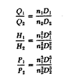
However, the various assumptions on which these relationships are based are rarely giving precise answers. Flow angles and the resulting velocity relationships are being disturbed by trimming. Experience shows that in real-world situations a reduction of impeller diameter greater than 15% of the original full diameter should not be allowed. To be on the safe side and so as not to cut too much, a prudent pump specialist will look at the mathematically derived diameter reduction (sometimes called the “fan law”) and then make a trim cut of only 70% of what the Euler-based fan law math requires.
Suppose, as an example and with no speed change, we wanted a pump head reduction from previously 680 ft to a new head of 580 ft. Suppose also we had an original diameter D1 of 13.00 inches and wished to determine the new diameter D2. After doing the algebraic transposing and square root extracting, we quickly find a new diameter of 12.14 inches—93 % of the original. Using the 70% rule we would now remove not 13.00 – 12.14 = 0.86 inches but, instead, only (0.7)(0.86) = 0.6 inches. In other words, field experience tells us the impeller should be trimmed to 12.4 inches. It may not be the exact needed diameter, but we will have avoided the risk of trimming off too much metal.
Good practice would be to trim only the vane tips (Figure 3b) and to leave both the impeller cover (sometimes called impeller shroud) and disc at the recommended Gap “A” diameters. Best practice would be to cut obliquely (see Figure 3, c and d) for greatest structural support and to ward off resonant vibration. Vibration of unsupported regions can lead to cracks and failure.
With oblique cuts, the average diameter D’ is used as the relevant diameter D2 in the Euler equation. Either oblique cutting or partial removal of unsupported regions (called “scalloping” in Fig. 6) is done to reduce the risk of fatigue failure.
Impeller wear rings
Modern process pump impellers are commonly fitted with plain wear rings. Wear rings separate regions of high pressure (discharge) from regions of low pressure (suction). Wear rings are considered replaceable parts and the gap between stationary (casing-mounted) and rotating (impeller-mounted) wear rings should follow the guidance found in API-610.
Most wear rings are plain cylindrical, although step and labyrinth-types (Figure 4) are occasionally used in efforts to reduce leakage flow. Their effectiveness does not appreciably differ from that of a plain wear ring. Time and effort needed to gain marginal improvement by implementing clearances 1 and 2 (“b” on right of Figure 4) is rarely worth it.
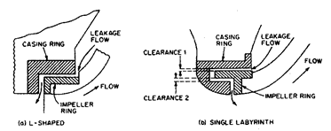
Fig. 4: L-shaped (“a”, on left) and labyrinth-shaped impeller wear rings (“b”, on right) Source: Ref. 2
Wear rings with enhanced contours (Figure 5, right side) make good use of the simple hydraulic vortex principle and are considered effective low-cost means of optimizing impeller performance (Ref. 3).
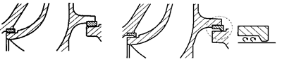
Fig. 5: Conventional wear ring profiles (left) and enhanced contour wear rings (right) Source: Ref. 3
Vane tip overfiling and underfiling
All impeller tip cuts and especially trim cuts across the entire impeller diameter (as done in the center illustration in Figure 3) produce blunt vane tips and hydraulic disturbances. These disturbances can be lessened by modifying the blunt vane tips by overfilling or underfiling (Figure 6).
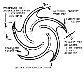
Fig. 6: Vane modifications suppress flow disturbances and vibrations
Removing metal from the leading edge of a vane tip is called “overfiling.” The region from which metal is to be removed by tapering and blending-in is shown as “L”. A guideline value for length “L” is 30% of the impeller radius R (or 15% of the impeller diameter). The vane tip width or thickness would be reduced to roughly 50% of its previous blunt edge width and metal removed so as to blend-in without creating a step or ridge. So as not to compromise strength and resistance to erosion, even a “sharp” tip should not be thinner than 8 mm (~5/16th inch).
“Underfiling” is the term used for metal removal from the trailing edge of the impeller vanes. About 4% additional head can thus be gained near the best efficiency point (BEP) and the H-Q curve is shifted slightly to the right. In other words, the liquid channel has been marginally enlarged and impeller performance is enhanced somewhat.
We chose a semi-open impeller (Figure 6) for ease of illustration only. It should be noted that scalloping, –i.e. the removal of unsupported material between vanes–is generally done on the shroud (cover) of a closed impeller. This scalloping reduces resonant vibration and fatigue cracking risks (Ref. 1).
What we have learned
Doing things right would include allowing no shortcuts on impeller technology.
- Observing gaps “A” and “B” and doing oblique impeller trims is Best Practice. Inculcating a mindset that is uncompromising will pay back handsomely for decades. Best-of-class performers easily reach pump mean-times-between failure (MTBFs) of 6, 8, and even 10 years (Ref. 3).
- Scalloping reduces the risk of crack formation and fatigue failure.
- Enhanced contour wear rings are simple and relatively effective performance enhancers.
- Some cooling fans are far too small to be of any value and cooling fans are often unnecessary on pumps.
- Making it a practice to allow deviations and accepting them will soon make deviations the “new norm.” Allowing deviations to add up is a huge risk; it will certainly prevent a plant from ever becoming a best-of-class performer.
- When 4 or more deviations are allowed to exist on a pump, early failure of the process pump is a virtual certainty. You will always pay a penalty for normalizing deviations.
References
- Bloch, Heinz P. and Allan Budris; “Pump User’s Handbook: Life Extension,” 4th Edition, (2014), Fairmont Publishing, Lilburn, GA, ISBN 0-88173-720-8
- Bloch, Heinz P.; “Pump Wisdom: Problem Solving for Operators and Specialists”; (2011), Wiley & Sons, Hoboken, NJ; ISBN 9-781118-04123-9
- Bloch, Heinz P.; “Petrochemical Machinery Insights,” (2016) Elsevier Publishing, Oxford, UK, and Cambridge, MA, ISBN 978-0-12-809272-9
Why Pumpsets Should Not Be Installed in “As-Shipped” Condition

Comments