I had the occasion to read the owner’s manual for my car the other day. As I read, I became intrigued by the information it didn’t offer.
For instance, the manual showed a cartoon picture of the dashboard. An arrow pointed to the gasoline gauge. Another arrow pointed to the low-fuel warning light. Another cartoon picture showed the gasoline nozzle door and filler cap. The words in manual read, “Turn-off the engine to add fuel. Use regular (89-octane) gasoline.”
It didn’t offer any rules on when to add gasoline. It didn’t say how many miles I could drive after seeing the low-fuel light. It offered no information on using higher-octane gasoline, or gasoline with ethanol.
On another page, a cartoon picture showed the clutch pedal and the transmission gearshift. The instructions said to depress the clutch pedal before changing gears. But there were no rules on how far to depress the clutch pedal. No rules explained at what speed I should shift from second gear to third gear, or when I might downshift. The car companies assume we already know these rules.
Likewise, it is assumed that we already know the rules omitted from the owner’s manual of a new pump. So, I thought it would be useful here to cover some of the Pump Guy’s unwritten rules for pump operation.
You can drive your car around the block and perceive a problem with it. You can observe your kids, look them in the face, and perceive if they have a problem, or if everything is going well. Most people have one or two cars, and one or two kids.
 |
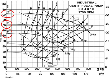
| You can see the shutoff head of the 10-inch impeller is 103 feet. The shutoff head of the nine-inch impeller is 81-ft. The shutoff head of the eight-inch impeller is 64 feet. |
At work, you might be responsible for the reliability of 50 or 300 centrifugal pumps. How can you stand next to one of these pumps, observe it, and perceive if the pump is sick or healthy? (No one teaches this at the university!) The following are a few generally accepted rules to keep in mind.
Rule No. 1: At 1,800 RPM, the impeller diameter in inches, multiplied by itself (or squared), is approximately the shutoff head of the pump in feet.
Why does the first rule begin with 1,800 RPM? In the states, most industrial pumps are powered by an electric motor on 60-Hz electricity. The most popular industrial electric motor (88 percent) is a four-pole motor, meaning the rated velocity is 1,800 RPM. (The motor may have a slip factor, so the actual speed might be 1,780 or 1,750 RPM. This is indicated on the electric motor identification tag.)
What is the shutoff head? The shutoff head is the beginning of the pump curve. It represents maximum elevation (in feet or meters) at zero flow. The performance curve proceeds to and ends at a point called maximum flow at zero elevation.
How do you begin with inches of impeller diameter and end with approximate feet of liquid elevation? It’s too complicated to explain in this short column, but that’s the way it is. (If you would like more in-depth discussion of this issue, I encourage you to attend my next Pump Guy Seminar. See the promo box at the end of this article for details.)
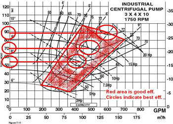 |
| The BEH of the 10-inch impeller is 88 ft., about 85 percent of the shutoff head. BEH of the nine-inch impeller is 70 ft., about 85 percent of the shutoff head. BEH of the eight-inch impeller is 54 ft., about 85 percent of the shutoff head. |
Why do you say, approximate? It’s just a rule or guide. It isn’t a law. It is accurate within about 5 percent. There are variables that affect the result.
What if the pump/motor is not spinning at 1,800 RPM? We’ll cover this in a future “Cheat Sheet” article.
Rule No. 2: The best efficiency head (BEH) of the pump is approximately 85 percent of the shutoff head.
Rule No. 3: Operate the pump at, or close to, the BEH.
The pump doesn’t want to run at shutoff head. It wants to run at the BEH or the best efficiency point (BEP) on the curve. On most pumps, the BEH is approximately 85 percent of the shutoff head. In almost all cases, the BEH is somewhere between 80 percent and 90 percent of the shutoff head. So, 85 percent is a good starting point to determine the pump’s head and flow.
Do these three rules apply to all pumps? They apply to about 88 percent of all centrifugal pumps in general industrial service. They don’t apply to special or exotic design centrifugal pumps or positive-displacement pumps.
What can I do with this information? Let’s say you’re standing next to a centrifugal pump mated to a four-pole (1,800 RPM) motor. The pump/motor is properly assembled and installed. The pump and motor shafts are aligned. The pump shaft is straight. The 13-inch impeller is balanced. The foundation is adequate. The bearings and seal are adequate and properly installed. The pump elevates cold water into an open vessel.
The differential pressure across the pump, as recorded on the suction and discharge gauges, is 46 PSI. The gauges are calibrated, accurate, and adequate. Is the pump sick or healthy?
From the first rule, this pump should have a shutoff head of approximately 170 ft. (13² = 169). From the second rule, you would expect this pump to have a BEH of approximately 144 ft. (169 x 85 percent = 144).
Because the given liquid is cold water, this pump wants to inject approximately 60 to 65 PSI into the system (144 ÷ 2.31 = 62.3 PSI. See “Cheat Sheets: 2.31 or .433,” Feb. ’08, page 40). Therefore, 46 PSI differential pressure is unacceptable, and this pump is sick.
What do you mean, this pump is sick? The seal and bearings are stressed. You can expect premature failure. Your seal and bearing sales people may pitch a tent in your plant and propose a mutually beneficial alliance. Yeah, right!
You can expect mysterious vibrations. The vibration technician’s report will say, “Undetermined vibrations. Engineer out!”
This pump may go into cavitation and might repeatedly trip the breaker on the electric motor, or fry the windings. This pump will be a constant headache with repetitive maintenance and failures. The reliability engineer might declare this pump a “bad actor.” Get off the stupid train!
How would you fix this pump? Start by increasing the resistance on the discharge piping. This would increase the differential pressure across the pump.
If the problems are mysterious vibrations, with bearing and seal failure, why don’t you tear apart and rebuild the pump? Why do you begin by adjusting the resistance on the system piping? (This will be covered more in-depth in a later Cheat Sheet.)
People, about 80 percent of what you perceive to be mysterious pump, bearing, and seal failure is not mysterious at all. The pump is indicating the problem for hours, days, and weeks before the breakdown occurs. Learn to interpret your curves and gauges.
Larry Bachus, founder of pump services firm Bachus Company Inc., is a regular contributor to Flow Control magazine. He is a pump consultant, lecturer, and inventor based in Nashville, Tenn. Mr. Bachus is a member of ASME and lectures in both English and Spanish. He can be reached at larry@bachusinc.com or 615 361-7295.
This article originally appeared in Flow Control magazine. If you would like to learn more, visit: http://www.FlowControlNetwork.com/PumpGuy


Comments