Authors: Ross Waters, President of CGIS, and Malcolm Harrison, Fluid Equipment Consulting Inc.
This article is part of a 5-part series which discusses valves in severe abrasive service. In Part 3, we discussed valve options for low pressure systems. Now, we will discuss valve options for high pressure systems.
High pressure systems typically operate above ~10MPa but owner’s choice may dictate the use of common valve types in all systems, within the same plant. The best choice for these systems would be ball valves with metallic seats.
Metal Seated Ball Valve Types:
- Fixed seat design, where the seat is an integral part of the body.
- Fixed seat design, where the seat is welded in-place.
- Fixed seat design, where the seat is retained by a bolted ring.
- Loose seat design, where the seat is allowed to float in either direction depending upon pressure.
- Loose seat design where the fluid pressure is allowed to force the seat against the ball surface (trunnion mounted design).
All metallic seated ball valves must have a sealing seat and ball that is protected from the erosive (and in some cases corrosive) nature of the slurry. Most common for erosion resistance is a thermal spray hard coating technologies such as High Velocity Oxygen Fuel (HVOF). This method utilizes confined combustion and an extended nozzle to heat and accelerate the powdered coating material. Typical HVOF devices operate at hypersonic gas velocities, i.e. greater than MACH 5. The extreme velocities provide kinetic energy which help produce coatings that are very dense and very well adhered in the as-sprayed condition.

Figure 6: HVOF Coating of Ball Component
Another method used when there is potential corrosion capability of the slurry is Plasma Spray. The plasma spray process uses inert gases fed past an electrode inducing the “plasma” state of the gases. When the gases exit the nozzle of the gun apparatus and return to their normal state, a tremendous amount of heat is released. A powdered coating material is injected into the plasma “flame” and propelled onto the substrate. Ceramic Coatings are most often applied using plasma spray due to their high melting temperatures (Often > 1900 C). Several types of ceramic coatings can be applied using plasma spray.

Figure 7: Plasma Spray of Ball Component
For all thermal spay coatings, the coated parts are then lapped separately before mate lapping, where the contact surface becomes so highly polished that small particles cannot pass between these parts, in a fully assembled valve. There are also variations on the basic thermal spray coating where nanostructured coatings are used to produce a highly dense coating that is almost totally impervious to corrosion.

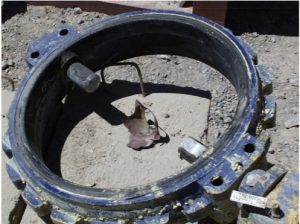
Figure 8: Coated and Mate Lapped Loose Seat Component
In all cases the purpose of the coating is to protect the internal components of the valve from the process fluid. In some applications where abrasion is very high, even the bore of valve is coated for protection from erosion.

Figure 9: Internal View of Ball Valve Showing HVOF Bore Coating
APPLICATION EXAMPLES IN HIGH PRESSURE

Figure 10: Pipeline Station Isolation “Wear and Seal” Arrangement
Wear and Seal
In a “Wear and Seal” (also known as martyr and master) arrangement the downstream valve is cycled first taking the wear of the flowing slurry. After the valve is closed the upstream valve is then cycled with no differential pressure ensuring secure isolation of the pipeline.
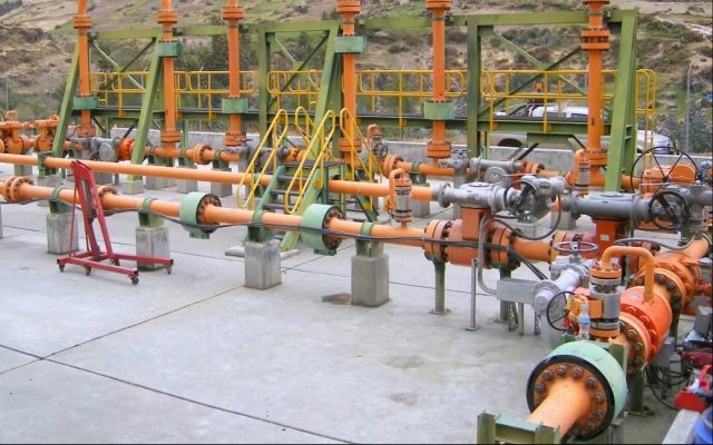
Choke Stations (see image at top of page)
Particularly with gravity systems and also for pumped systems, accumulated pressure must be dissipated for safe pipeline operation. Choke stations are a method and apparatus for protecting against the abrasion of pipe walls in a slurry pipeline caused by slack flow, when the pipeline is operated in the batch mode (water or various slurries are delivered through the pipeline). Pressure transducers sense the pressure at each relatively high point of the pipeline as an interface between a water batch and a following slurry batch passes that point. When one of the sensed pressures falls below a predetermined low value of pressure, a control device actuates valves that divert the flow downstream in the pipeline through a staged choke containing flow restrictors, thus raising the fluid pressure in the water batch which then counteracts the effect of the static head of the slurry batch. The flow is redirected away from the staged choke when one of the sensed pressures exceeds a predetermined high value of pressure, thus lowering the fluid pressure and preventing pipe wall overpressure. The choke branch isolation valves need to operate under high differential slurry flow conditions and provide zero leakage when closed.
Valve Station Isolation (Bidirectional)

Figure 12: Pipeline Isolation Valves for Bidirectional Operation
When a long distance slurry pipeline has extended portions of the line that may see pressure in either direction, valves are needed that can seal from either direction or should be installed such that when they are closed they see pressure on the preferred sealing end. These valves can see high cycling under conditions where the abrasive slurry may fall out of the preferred flow regime. Designing the valve internals for protection against erosion is critical in maintaining reliable operation.
About the Authors
As the President of CGIS, Ross Waters has dedicated 35 years of his life to serving and improving the valve industry. Ross started CGIS, a valve distribution company, in 1980 in a small office in Vancouver, Canada. Thirty-five years later, the business has grown internationally and now serves clients and industries worldwide. Ross is the driving force behind increasing awareness of Severe Service Valves and is part of an MSS task forcewriting its definition. He has attended numerous conferences around the world presenting his paper, “Defining Severe Service Valves” and is well onto establishing himself as the leading expert in Severe Service. Ross is also an avid member of ASTM International G04 and has served as an expert witness.
Malcolm Harrison was born and educated in the UK and received a bachelor’s degree in mechanical engineering. After a successful career with major EPC’s working as a mechanical and piping design engineer, Malcolm relocated to the USA in 1980 to work for Bechtel in San Francisco. He eventually entered the world of valves sales in the early 1990’s. First with a specialist valve sales representative company and then as mining products industry manager with Houston-based, ValvTechnologies. In late 2014 he retired and started his own consulting company, Fluid Equipment Consulting. Malcolm now uses his vast experience to offer subject matter expert services related to all types of valve requirements.

Comments