In this world of ever advancing technologies, the water and waste water pumping industry has seen an explosion in the use of highly technical variable frequency drives, or “VFD’s”.
Known by many generic names, and produced by manufacturers worldwide, these technical marvels have opened the doors to endless possibilities, in pumping systems controls.

This expansion of possibilities has opened up many methods that can be used in controlling the discharge pressure in a pumping system.
In this paper analyze the main methods for controlling pressure in a water/wastewater application, and in doing so will also discuss the primary, and advanced methods of pump, motor, and piping protection. A side benefit of VFD’s is that the operator is also able to monitor system status and ongoing electric power consumption. Undetected inefficiencies can significantly increase utility bills, that when added among many systems can cripple the owner’s maintenance budget or utilities managing many systems.
Controlling Pressure
The common components for controlling pressure in a pump system include:
- Manual Pressure Switch
- “PRV” Pressure Reducing Valve
- Pressure Transducer
Manual Pressure Switch
This method has been the mainstay of liquid pressure systems for many years. It has served the industry well and remains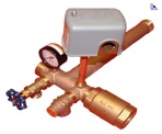 the pressure controlling method for a large percentage of systems. Systems utilizing this method will experience pressure increase and decrease from start to stop points based on pressure in their system, or will need to substantially increase the pressure tank in the system in order to decrease the pressure differential and still maintain the minimum run time required by pumps.
“PRV” Pressure Reducing Valve
There are two categories of PRV used in systems, depending on location and application. For municipal systems, the incoming water to a residence or business is considerably higher than needed.
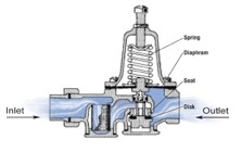
This is intentionally done to allow for variations due to elevation, demand fluctuations, and fire suppression requirements that typically come off of the same municipal system. The PRV in this case eliminates or mostly eliminates pressure variations by simply stopping excess water from flowing beyond the PRV. From an energy consumption point of view, this is an acceptable method given that pressure must be constant within one system throughout a whole community where there are huge variations in volume and pressure needs.
A second PRV method employed for systems, is commonly referred to as a cycle stop valve or CSV.
 These units aredesigned to limit the maximum pressure in a system by restricting the output through the valve based on thepressure on the output side similar to more common PRV’s. CSV’s also do two more things. When the pump turns on at the low pressure switch point, the valve causes the buildup of pressure to a desired point between the low and high and then reduces the output volume by restricting it to only the amount required to maintain the desired point while also maintaining a minimum amount of flow to prevent damage to the pump. When usage shuts off completely and the set pressure is reached, the valve then diverts the flow through a bypass to the pressure tank to restore the backup capacity. This method maintains a constant pressure for a time, however allowing the pump to run at maximum head conditions and restricting the flow to this degree, greatly reduces the running efficiency of the pump.
Pressure Transducer
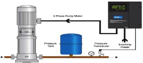
 The pressure transducer acts simply as an information source. This information is provided typically to a variable frequency drive or VFD. The VFD is able to use this information to control the amount of energy sent to a motor/pump and slow down or speed up the pump to maintain a constant pressure. This is done by changing the frequency of the electrical pulses through what is known as an inverter. This allows for full control of the output of the system.
Coupled with a modestly priced VFD the user is also able to monitor and subsequently protect the system from damage.
The Historical Problem
Water pressure systems historically included a pump/motor with capacitor starter, controlled by a simple pressure switch that would turn on the pump when the pressure in the system dropped below a pre-determined “start” point, and turn off the pump when the same switch would open back up. The differential between the “start” and “stop” points and the size of the pressure tank attached to the system, determined the run time of the pump. To avoid excessive “cycling” of the pump, the pressure tank was sized to allow for the minimum run time required, based on the manufacturer’s recommendation to ensure long life of the pump/motor combination and to maintain the warranty.
Problems occur when the operating conditions of the system change. The following are variables that, when changed, affect the system’s ability to maintain intended results.
- Demand on the system changes
- The supply reservoir cannot replenish itself at the rate required
- A broken line in the system
- The pump/motor begins to fail
- A foreign object gets lodged in the pump
Without a method of detecting these conditions, the system continues to run; causing physical damage to pumping equipment and potentially causing substantial physical damage beyond the system itself. Even before noticeable external damage, substantial increases in electricity usage results from most of these conditions, when not detected promptly.
The Solution
A properly sized variable frequency drive, motor and pump, coupled with a pressure transducer, provides for; a constant pressure within the pumping range, maximum energy efficiency for the given system, and peace of mind knowing the drive is monitoring the system, shutting it down to protect it, other equipment in the system, and external physical damage in the area. Let’s look at each of these benefits in more detail.
Consistent Performance
Society has come to expect that when they turn on the faucet, the water will flow at the same rate and pressure regardless of how many people are using the system at one time. The VFD is best suited to provide this “variable” rate and still maintain an efficiently running system. Without getting too technical, the drive does this by reproducing the AC sine wave at a variable frequency. This frees us from the limitations given by the electrical utility that typically provides electricity at sixty pulses per second or 60 hz. Historically motors were designed to run most efficient at this speed; however new electric motors, windings and insulating material, are designed specifically to take advantage of this ability. These motors are “inverter duty rated”. By changing how fast the pulses are fed to the motor, the output of the pump can be controlled variably without restricting the flow and reducing efficiency of the pump.
Maximum efficiency
Getting a constant pressure by controlling the electrical energy sent to the motor, rather than restricting the output of the liquid, VFD’s are able to gain efficiency over other methods, and reduce the utility cost of the system.
Monitoring, Protecting, and Notifying
The monitoring abilities provided by modern VFDs, are only limited by the imagination of the designer and the ways in which the system is intended to be used and protected from damage. The most commonly used protections in water pressure applications are discussed below.
System Pressure
Basic to water systems, the pressure of the water is monitored constantly. This information is used in many ways to determine the health of the overall system.
Low/No Flow (also known as dry run)
When the system is properly installed, the normal operating speed will be established that determines how fast the motor needs to run to maintain the system or “set pressure”. If the system is not maintaining the pressure required within the normal speed range, it assumes there is not enough water and will stop running to protect the pump from “dry running”
Seal Fail
This protection requires a pump motor equipped with a sensor that can detect when a seal on the motor has failed and there is water getting into the motor. Typically used in larger systems, this notifies the user that maintenance is required to restore the system to health.
Motor Overload Protection
By setting the maximum amperage based on the nameplate, the motor is not damaged by over-current. Branch circuit protection is still provided by the breakers required by local code. Advanced functions available in most modern drives, allows that the drive will not only shut down on over-current, but will also report by error code when the condition occurred. This is very helpful when diagnosing the root cause of the failure; during startup, running, or deceleration.
Under-voltage
Damage to the motor is prevented should there be a brownout or other under voltage condition on the input line power.
Three Phase Power Issues
In three phase systems, the VFD protects the drive and motor, should an unexpected phase loss occur in the incoming power supply. Parameters can also be set to protect from an un-acceptable amount of phase imbalance. These measurements are on the incoming side of the VFD, and depending on how the drive is sized; a larger amount of error can be tolerated, without affecting the output of the drive to the motor. In fact, many drives are used just for this purpose. Running a 3 phase motor, where 3 phase power is not available, drives can be sized and setup to convert single phase incoming power to three phase output (motor) power.
Self Protection
In addition to the advanced protections for the pump, motor and piping system, modern VFD’s have a multitude of protections built into the drive to protect itself from being damaged, provided it was installed and setup properly to match the other components in the system.
Notification of Protections
All these represent a large advancement in protecting your pump, motor and piping; however does nothing to notify you if the system is shut down as a result of one of these protection faults. If your system is critical, you will want to consider adding a remote monitoring or notification module. These systems are as simple or advanced as needed to match the desired notification level. Full “SCADA” (Supervisory Control And Data Acquisition) systems are quite advanced, used typically in large scale systems, and can add a large expense to the initial and monthly expense of operating the system.
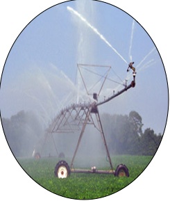
For most irrigation, well pumping, and pressure boosting systems, an economical add-on that offers a cell phone based notification when faults occur, can add peace of mind when the system is in an area not checked frequently to prevent physical damage should the system shut down.
No shortcut for good design
While modern VFD’s provide a much higher level of monitoring and protection for your system, drives cannot make up for a poorly selected motor and pump combination. Solid system design and an up-front investment is money well spent when installing a pressure controlled water system. One of the most common issues blamed on VFD systems is asking a constant pressure system to operate on the flat portion of the pump curve. If the requirements of the system will operate the motor at the top 15-20% of the frequency available, there is little range left to allow for a variable flow. If your system operates satisfactory at 60hz yet is at no flow (dead head) at 50-55hz. your system is prone to issues in the future. This condition gives the variable frequency drive an unwarranted bad name when the real issue is in the design of the pumping system itself. There is no substitute to having a good, well designed setup by a reputable company with experience with these types of systems.
Summary
The large supply of VFD’s from a variety of manufacturers, and the ever advancing technology built into them, is proof in and of itself that this technology makes sense for advancing the reliability and protections available to systems in this market. It also lends well to the “smart grid” technology and connectivity necessary to monitor and control energy usage throughout the life cycle of a pumping system. The use of variable frequency drives in this market has now gone beyond critical mass and its future use in this market will continue to increase.


With a VFD constant velocity water system if the pressure sensor(transducer) fails what stops system bursting piping? Should there be a PRV installed somewhere to piping? Kind regards, Chuck