
A colleague of mine, Peter de Place Rimmen, read my previous blog post on product reliability and while there’s nothing wrong in what I wrote, he did send me a bunch of material on more modern approaches to determining product robustness, rather than product reliability. I finally got time to go through some of this material and it is exiting reading and does indeed provide a very different and more true to the application view on reliability.
Robustness Validation Methodology
In essence you can say that the modern approach is more like a systematic analysis of the actual usage circumstances and their impact on the products installed. Thereby providing a more realistic view of product life time expectancy can also be provided and this is after all, what we are really interested. Compared to more traditional methods, you need to know a lot more about the actual expected usage conditions, but you can then also much more accurately say what a customer can expect during the life time of the product. Several electronics manufacturers have in recent years adapted this Robustness Validation Methodology, which you can find described in more detail in How to measure lifetime for Robustness Validation – step by step by ZVEI.
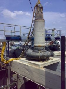
This means that you first have to collect a lot of data on what the stressors are for the product. When looking at a variable frequency drive (VFD), stressors will typically be things like supply voltage, temperature, humidity and vibration. The normal conditions for these stressors then needs to be determined for the installation and regular appearing outliers need to be evaluated.
Defining the Application
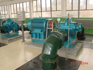
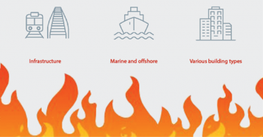
Already now it’s clear that for a pumping application, there are several different installations to evaluate, as the behaviour of the stressors are very different in ex. mining and commercial buildings. Even for commercial buildings the difference are huge depending on the geographical area in which the drives are installed.

To accommodate the analysis standardised environments (mission profiles) are defined based on the main segments where a VFD manufacturer’s products are installed. This means that it is important in the evaluation of a product to discuss the actual application of the drive, since only based on the environmental conditions of the application can it be determined what the life expectancy of a drive would be.
Accellerated Test Model
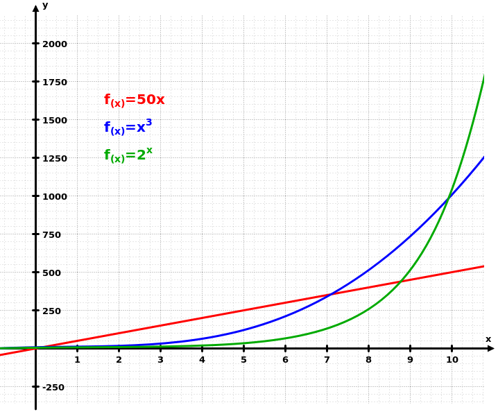
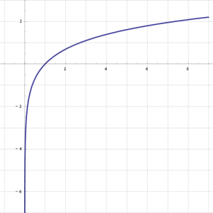 In order then to actually test the product reliability of the drive, it is necessary to find out the duration of the stress exposure and also the intervals. Also the behaviour of the VFD to the stressor is a very important factor, as the test needs to emulate the same failure mode. Some failure modes are linear, so increasing the voltage 10% also increase the stress 10%, but others have a logarithmic or exponential relationship and now suddenly a minute change in the stressor can have almost no effect or actual detrimental effect on the drive.
 Based on this information accelerated testing can be defined, increasing the stress level and reducing the cycle time, so we can actually test the failure modes as close to real life, but in a much shorter time. We need to have completed the testing before we launch a new VFD or a modification to an existing drive, so we know it will have the expected product reliability while selling the product, instead of when they start failing in the field. It must however also be carefully considered that failure modes are not introduced by the increased stress, which would never appear in the field. An example mentioned by ZVEI is to never exceed the melting point temperature of a molding material, as this would not be representative for the application (unless off course a wrong molding material has been applied in the design).
Specifying VFD Environments
When specifying drives, however, this also means that manufacturers more often will require an actual specification of the environment, before making compliance statements to product life time. This requirement is quite logical, but put a lot more requirements on the knowledge of the end use of the product.
As an example, an engineer is specifying a booster set for a hospital and wants a 10 year life time. In most cases we would know the geographical location, since we know where the project is being planned. What is not specified, however, is the installation location.
If the drives operating the booster set are installed in an air conditioned motor control centre, then operating conditions will be optimum and life expectancy more easily estimated.
If however the drives are installed on the pumps and the pump room is not air conditioned, then suddenly the geographical location becomes very important, since we might then experience temperatures exceeding 50ºC/122ºF and we’ll have vibration from the pump. This immediately increases the stress on the drive and potentially reduces the life expectancy of the VFD and makes the accurate assessment of product reliability more complex.
A reduction in life expectancy of a drive is not necessarily a problem at all. If a drive has been designed for the operating conditions and the design has gone through a thorough robustness validation, it could still easily meet the required product life time. If conditions were more ideal, it would far exceed the product life time, which would likely mean that it to some degree is over specified for the application and cost has been added to increase robustness beyond customer specification.
Deciding What to Design for
A design is always a careful balance between the most extreme requirements and the market price levels for the average applications. This is also why many VFD manufacturers have several different product series targeting specific segments and applications. While a product may have the same physical appearance changes may have been made to optimize the cost to meet market prices levels. This could be using less sturdy capacitors for lower tier applications, or adding coating and ruggedisation for harsh environments with corrosive agents in the air and high vibration levels.
There is an excellent example of how to make a step by step analysis of the failure mode, starting from failure mode identification over multiple devices testing to account for part to part variations, to an analysis of the three stages of failure:
- Early life extrinsic failure (typically manufacturing defects)
- Useful life random failures (tolerances and unforeseen events cause a moderate failure level)
- Wear out intrinsic failures (component end of life accelerate failure rate)
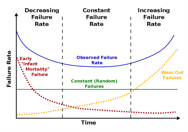 These three modes will create a bathtub curve which defines the life time of a product. For products requiring a long life time the distance in the bathtub between #1 and #3 should off course be as long as possible.
Some would say that long life time is always desired, but that is not the case. I have talked to people in several different industries and while a hospital need products with a long life time in mostly good environmental conditions, a cement factory, which due to the environment need the machinery exchanged every 3-5 years, has a focus on very high up time during a much shorter period, which has different requirements to the product reliability of the drive. Some industries even have an expectation to exchange all electronics on a regular basis because they know it’s almost impossible to build electronics which can last for a long time anyway.
Failures Accumulate Over the Product Life Time
Below graphics show the integrated function of the bath tub curve which is called the MCF-curve (Mean Cumulative Function). The advantages with this curve are that it can be used for design target and this can be compared with the field failures.
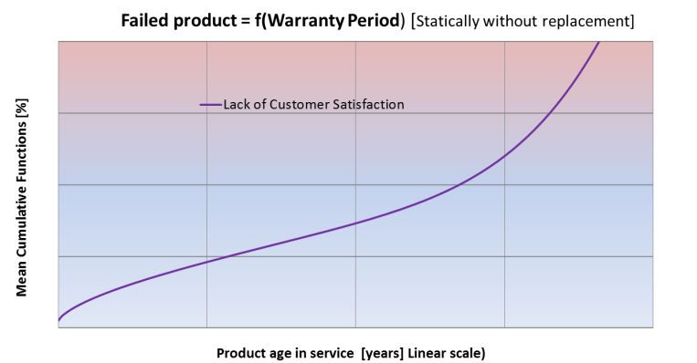 Everyone knows that once a product fails, it doesn’t just drop out; it remains in the statistic as a failure and contribute to the customers perception of product quality. Below curve provides a simplified view on “Lack of Customer Satisfaction” as a function of the cumulative failures of a product.
It is therefore important to understand how failures accumulate over the life time of a product and what influences the total curve of cumulative failures, in order to influence customer satisfaction with the product.
If you look at the curve of the total mean cumulative failures (purple below), this should be split into 4 distinct curves, each contributing to the above mentioned bath tub curve.
0-time failures (red), meaning dead on arrival, are typically failures occurring in transport, installation or due to poor instructions. These types of failures are often due to lack of consideration for the practical handling of a product before it is put into service.
Early failures (green) are typically manufacturing or design issues with the product and will have the highest failure rate early in a products life time and will then flatten, as all influences not compatible with the application by design or manufacturing will be triggered early and cannot be reintroduced in the application.
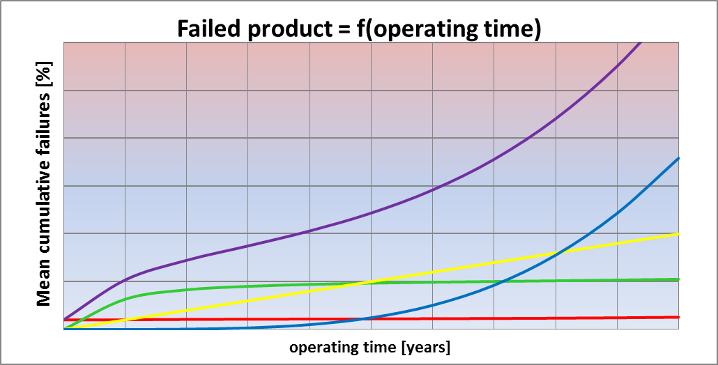 Lack of design robustness (yellow) is a constant curve and is on the other hand often because of a product not fulfilling the actual requirements of an application. In these cases either the mission profile was not clear from the specification or a product was selected to reduce cost, though it didn’t meet the specification. This type will be low initially, as the stress in the application has not yet affected the product, but will have a constant rate, simply because it is the nature of the application, when a specific product is applied.
Degradation and end of life for components (blue) is the intrinsic failure mechanism, which is determined by specific components within the VFD degrading to a level, where the drive no longer meets specification and fails, or the component itself reaches end of life and fails.
Specifying the True Need
As a specifier it is important to understand all the environmental factors in the installation and make sure these are defined in the specification. I had a case some years ago with a large plant where drives were corroding within 6 months of installation. According to the end user, motor control centre was well ventilated and filters were installed and maintained to protect the drive against all dust in the facility, so environmental factors should be under control. The specification had called for compliance with IEC 60721-3-3 class 3C2, so moderate coating had been applied. Upon making a measurement of the air inside the panels however, there were high concentrations of sulphur and high humidity, thus causing sulfuric acid corrosion on the drive terminals. Levels were significantly higher than specification had stated. After this drives with higher protection were installed complying with IEC 60721-3-3 class 3C3 and the problem was resolved.
There’s always a Margin to Consider
As a manufacturer you need to understand the customer requirement specification and in your design take the component degradation into account. Traditionally designs have been made to meet the customer specification, but this actually means that after a certain period of operation, the actual product specification has degraded and now no longer meets the customer specification. In practical terms at the time of purchase, the product met all requirements, except the degradation was not taken into account, so the actual lifetime of the product would be less than specified, since the application requirements sometime after installation would degrade the performance and thus accelerate failures.
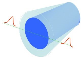 Peter also published a paper in IEEE JOURNAL OF EMERGING AND SELECTED TOPICS IN POWER ELECTRONICS, VOL. 2, NO. 1, MARCH 2014 together with some of his peers, where you will find also find The Rimmen Model (simplified version below) and a much more elaborate explanation to this requirement for designing with a robustness margin, to meet the customers long term expectations.
In both the ZVEI document and the IEEE paper you will find guidance to more documentation and for those wanting a deeper understanding of the subject, these are highly recommended.
Written by: Frank Taaning-Grundholm, Director, Global Strategic Customers, Fluid Handling

Comments